The difference between Multi Jet Fusion (MJF) and Selective Laser Sintering (SLS) in the case of precision manufacturing may influence your production results widely when choosing the best 3D printing technology to implement on the assembly line. The two technologies are superior in various situations, and it is very important to know the difference between the two technologies in order to get quality and affordable production by manufacturers.
Introduction to SLS and Quick Comparison to MJF
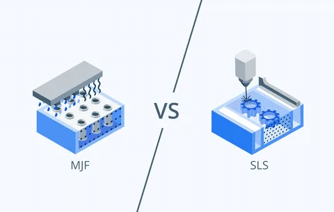
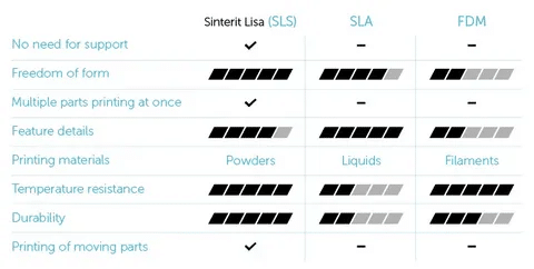
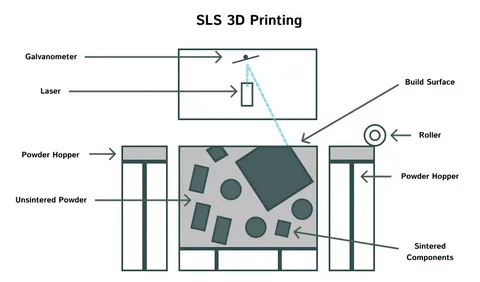
Selective Laser Sintering (SLS) is a powder bed fusion process which employs a laser to selectively fuse powder, generally nylon, into solid three-dimensional pieces. SLS was invented in the 1980s and is regarded as one of the foundations of industrial added-value 3D printing because it is used to manufacture complicated structures without the need to use support structures.
On the contrary, HP has introduced Multi Jet Fusion (MJF) technology in 2016 that is a more recent implementation of powder bed fusion. MJF applies fusing and detailing agents using an inkjet array to selective parts of a powder bed and subsequent heating elements fuse the material where fusing agent was applied.
Key Differences at a Glance:
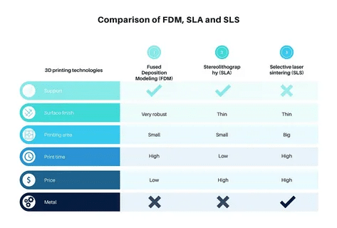
- Speed: MJF processing speeds through layers tends to be quicker
- Surface Quality: MJF normally comes up with smoother surface finishes
- Material Options: SLS has a wider material compatibility
- Cost Structure: the pricing systems at increased levels of production
Advantages and Disadvantages of SLS Compared to MJF
Advantages of SLS
Material Flexibility: The SLS technology can utilize almost all materials such as all grades of nylons, glass-filled nylon, as well as carbon fiber-reinforced materials and even metal powders in certain systems. That versatility renders SLS the perfect candidate in applications that need material properties.
Time-Tested Technology: SLS has been more than 30 years in development and its maturity has resulted in an established system of material, process and post-processing solutions. Such maturity reflects in predictable outcomes and well-established best practices.
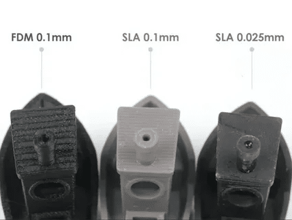
Fine Detail Capability: SLS is capable of good detail resolution that is useful on delicate geometries and thin walled structures experienced in precision work with molds.
None of the Support Structure Requirements: Similar to MJF, SLS does not need support structures, which allows intricate internal geometries and less time in post-processing.
Disadvantages of SLS
Lower Speed: Normal SLS systems do not layer as fast as the MJF does, and this may affect the production timeline of high volume batches.
Increased energy usage: laser sintering More commonly, laser-based sintering will consume a lot of energy per part compared to the MJF which uses heat.
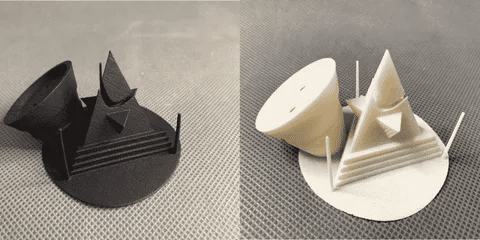
Surface Roughness: SLS parts have a slightly rougher surface than MJF which may mean that they have to undergo further post processing at applications that need smooth surfaces.
Complexity of Temperature Management: It involves use of heat-sets to maintain constant temperatures on build volumes that are generally large is likely to interfere with consistency in part quality.
MJF Introduction and Quick Comparison to SLS
Multi Jet Fusion is an HP technology that transforms powder bed fusion due to its laser-replacing approach of combining inkjet printing and thermal energy technologies. Starting with a thin layer of nylon powder and selective use of fusing and detailing agents by use of thousands of nozzles, the process continues. The heat is then evenly spread on the whole layer fusing material only in the areas on which the fusing agent was placed.
MJF Key Innovation: The detailing agent leaves sharp part boundaries with a higher surface quality and accuracy of dimensions due to the absence of fusion at the edges of the parts.
SLS Process comparison:
- Layer Processing: MJF uses layers and processes them all at a time whereas in SLS, each cross-section is laser-traced.
- Heat: MJF is characterized by even heating and selective application of agent; SLS is characterized by selective laser heating
- Agent Control: In MJF the dual-agent gives more control over the boundaries of parts and surface finish
Technology Comparison: SLS vs. MJF (Detailed Process Analysis)
SLS Process Details
SLS process has the following very important stages:
- Powder Preparation: Recycled and fresh powder are mixed till they attain the best ratios
- Preheating: The build chamber is given enough heat to get near the melting temperature of the material but not enough to reach it.
- Layer Spreading: A light coating of powder is placed upon the build platform
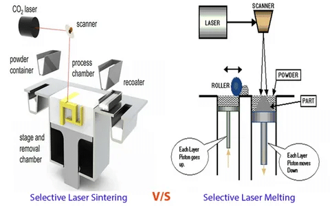
- Laser Sintering: A CO2 laser fusion is selectively achieved on the basis of the cross-sectional geometry of the powder particles
- Layer Repetition: The process is carried out layer by layer until made complete
- Cool Down: In the powder bed, parts cool at a slow rate to reduce warping
MJF Process Details
MJF process takes an alternate route:
- Powder Layering:Nylon powder is sprayed evenly on the build platform
- Use of Inkjet Arrays: Inkjet arrays use fusing agent on the locations where solidification is needed and detailing agent on part boundaries
- Thermal Processing: Heating elements evenly warm up the layer and melt together the material where the fusing agent got applied
- Layer Progression: This sort of progression is repeated layer to layer with accurate agent control
- Cooling: Temperate cooling avoids warping and provides stability in dimension.
Print Volume (Build-Size Comparisons)
SLS Build Volumes
Build volumes in industrial SLS systems more commonly vary between:
- Small systems 200 200 200 mm
- Medium Systems 300 x 300 x 400 mm
- Huge Systems: 600 mm or more in any direction
MJF Build Volumes
HP MJF systems already propose:
- HP Jet Fusion 4200: 280 380 280 mm
- HP Jet Fusion 5200: 380 x 284 x 380mm
- Industrial Series: Dimension of up to 406 x 305 x 406 mm
Volume efficiency: Both technologies are very efficient in the nesting of several parts in a single build which makes them effective in the utilization of volume. There is however an interdependency in the best packing strategy which varies with the technology depending on the processing mechanisms of the technology.
MJF vs. SLS Cost Analysis

Unit Cost Factors
SLS Cost Structure:
- Low Volume (1-10 parts): 15-50 bucks per part based on size and complication
- MediumVolume (10-100 parts): 8-25$ per part and volume discounts
- High volume ( 100+ parts): 5-15 dollars per part, nesting optimized
MJF Cost Structure:
- Low Volume (1-10 parts): 12-40 dollars per part, will likely be cheaper than SLS
- Medium Volume (10-100 parts) : $6-20 per part with good build packing
- High Volume (100+ parts): $4-12 / part, is frequently more cost effective to produce than SLS
Cost Influencing Factors
Cost of Material: The two technologies work with similar nylon materials, but as recycling rates and refresh ratios of powder become relevant aspects, they may cause variation in the overall material cost.
Processing Speed: MJF has a quicker layer processing that can be used to save costs on the machine time, especially when the production is of large quantities.
Surface finishing requirements: Surface finishing requirements can greatly contribute to the overall part cost, and MJF requirements are often low in amount of post-processing.
Should I Design Differently for MJF vs SLS?
Design Considerations for Both Technologies
Wall Thickness: Both technologies have the minimum reliable wall thickness of 0.8-1.0mm but there is a slight possibility to print even thinner with MJF as the boundaries are usually controlled better.
Both must have escape holes: to shell out unsintered powder trapped in closed volumes. Minimum hole size: 3-5 mm.
Tolerances: The dimensional tolerances the two technologies can deliver are similar:
- General Tolerances: Ranges less than 100 mm to, + 0.3 mm
- Tight Tolerances: +/- 0.1-0.2 mm can be obtained by this way of design optimization
MJF-Specific Design Guidelines
Surface Finish: The high-quality surface finish in MJF is great to use when you need any part that needs little to no post-processing. Use this quality of natural finish in the design of parts.
Detail Resolution: MJF has a higher capability to print more details on vertical as well as angled surfaces since the formation of the boundaries is controlled.
The Thin Features: The detailing agent used by MJF gives a superior control on thin features and sharp edges.
SLS-Specific Design Guidelines
Material Selection: utilize the expanded material capabilities of SLS when a particular application needs particular mechanical properties.
Complex Geometries: Dynamic Process Parameters The mature process parameters of SLS allow SLS to be dependable on very complex internal geometries.
Big Components: SLS systems can provide larger build volumes when the objects are too big.
Can MJF and SLS Be Used Interchangeably?
Application Overlap
Lots of applications can use both technologies successfully:
Prototyping: The ability of both to form functional materials at rapid speeds allows low-volume production Prototyping: Both remove the requirement of support structure in most cases Complex Geometries: Both allow the production of complex geometries
Technology-Specific Applications
MJF Advantages:
- Shopping products that need smooth surfaces
- Applications in which it is necessary to minimize the post-processing time
- heavy-duty production that is regulated by high quality principles
SLS Advantages:
- Applications needing special materials (glass), Carbon fiber)
- Components that require particular mechanical characteristics that are provided by SLS material only
- Components greater than MJF build volumes The items that are in the large-scale category are within the volumes of creation that exceed the MJF builds volumes
Decision Matrix
| ファクター | MJF Better | SLS Better | Equal |
| Surface Quality | ✓ | ||
| Processing Speed | ✓ | ||
| Material Options | ✓ | ||
| Build Volume | ✓ | ||
| Detail Resolution | ✓ | ||
| コスト効率 | ✓ | ||
| Technology Maturity | ✓ |
How to Choose the Right 3D Printing Technology
Decision-Making Framework
Step 1: Define Requirements
- Material properties and mechanical properties
- The level of finish requirement University of California, 1986
- Dimensional tolerances
- Volume and schedule of production
- Budget constraints
Step 2: Evaluate Technology Fit
- Compare availability of materials among technologies
- Evaluate build volumes needs
- Think over post-processing possibilities
- Consider cost implication throughout the production volume
Step 3: Consider Long-term Factors
- Future material and technology roadmap
- Supplier support and supplier reliability
- Compatibility with current manufacture processes
- Ability to scale capacity in the future production requirements
Recommended Decision Criteria
Choose MJF When:
- The first place is surface quality
- The levels of production are medium and higher
- Quick response times play an essential role
- The main concern is cost efficiency
- Normal nylon fits the billing
Choose SLS When:
- Special characteristics of the materials will be needed
- Altogether, large volumes of building are required
- They require maximum choices of material options.
- The stability of the process is vital in the long term
- It is meaningful to integrate with the workflows of existing SLSs
Design Tips for SLS
Optimizing Parts for SLS Production
Orientation Strategy: Orient parts so as to reduce the number of points of contact on the support surface and also to maximize surface finish on important places. Think of another way of part orientation in light of powder removal.
Web Thickness Optimisation: Ensure there is uniformity in the thickness of walls as far as it is possible. Avoid rapid transition of thickness which will cause thermal stress and warping.
Powder Removal Design: Add enough escape holes and have powder flow considerations in the designing. Multiple exits should be made possible along the complex internal channels.
Management of thermal: Design the parts with constant cross sections that have low thermal gradient during processing. When at all possible, large solid pieces should be hollowed.
Design Guidelines for HP MJF
Leveraging MJF’s Unique Capabilities
Optimization of Surface Finish: Make the parts designed to display the high quality surface finish that MJF offers. Surface orientation and feature positioning should be considered in order to reduce post-processing requirements.
Boundary Control: Use the fine boundary control limits of MJF and achieve sharp edges and grounds. Create complex details that would prove difficult using other technologies.
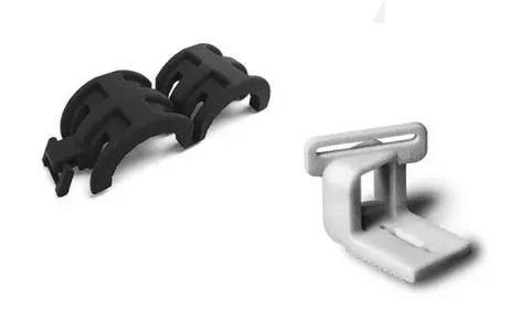
Multi-part Assemblies: Design multi-snap-fit assemblies and interlocking parts built to be printed as single-builds, and leverage the dimensional accuracy of MJF.
Texture Integration: Keep surface textures in the model, because with MJF, it is easy to recreate fine surface features.
Comparative Table of Key Decision Factors
| ファクター | SLS | MJF | Winner |
| Material Variety | Extensive (Nylon, Glass-filled, Carbon fiber, etc.) | Limited (Primarily Nylon-based) | SLS |
| Surface Quality | Good (Ra 3-6 μm) | Excellent (Ra 2-4 μm) | MJF |
| Processing Speed | Moderate (laser scanning) | Fast (simultaneous layer processing) | MJF |
| Build Volume | Large (up to 500×500×600 mm) | Medium (up to 406×305×406 mm) | SLS |
| Dimensional Accuracy | ±0.3 mm typical | ±0.2 mm typical | MJF |
| Cost per Part | $5-50 depending on volume | $4-40 depending on volume | MJF |
| Technology Maturity | 30+ years | 8+ years | SLS |
| 後処理 | Moderate requirements | Minimal requirements | MJF |
Materials, Surface Finishes, and Engineering Tolerances
Material Comparison
SLS Materials:
- PA12 (nylon 12): general purpose engineering plastic
- PA 11 (Nylon 11): The flexibility in a bio-based substitute
- Glass filled PA12: improved stiffness and thermal properties
- Carbon fiber PA12: Has a high strength to weight value
- DPA12: Aluminum-filled PA12: Aluminum-like look and characteristics
MJF Materials:
- HP 3D High Reusability PA12: High quality recyclability of standard material
- HP 3D High Reusability PA11: Impact resistant option that is flexible
- HP 3D High Reusability PP: Chemical resistance polypropylene:
- Special materials: Flame resistant, antistatic types Unless it is also stated that the materials are antistatic, this usually means that the materials are both flame resistant, and antistatic.
Surface Finish Options
As-Built Surfaces:
- SLS: A little bit rough surface (Ra 3-6 μm)
- MJF: Matt soft (Ra 2 -4 micron)
Post-Processing Options:
- Vapor Smoothing: Makes the surface smooth down to Ra of 0.5-1 um
- Color: Both technologies have radioactive dyeing capabilities Dyeing: Broad color choices are available in both technologies
- Machining: Critical finishing of surfaces
- mediablasting: surface texture blemish-free modification
Engineering Tolerances
Achievable Tolerances:
- Linear Tolerances: 0.15-0.3 mm variation on size of part
- Diameter of Holes: standard holes: +0.1/-0.2 mm
- Threading: Thread M3 and above that are suited to that kind of design
- Flatness: 0.1-0.2 mm over 100mm spans
- Concentricity:- _0.2 mm on mating features
結論
Your manufacturing needs, volumes of manufacturing, and the requirement of quality would identify which material you choose to use between MJF and SLS. MJF is also ideal in producing high to medium volume, cost-effective, and excellent surface quality. SLS has the advantage of better material options, more volumetric builds and provides the predictability of an older technology.
In case of precision mold manufacturing, the two technologies are able to provide the accuracy and quality needed in applications that have high demands. When you are deciding, take into consideration your particular needs as far as material properties and surface finish with regard to your volume production and cost restraint are concerned.
At Dongguan Zecheng Precision Mold Co., Ltd., we realize that the success of your enterprise depends on its proper choice of manufacturing technology. We have experience in precision manufacturing, and can advise you on the most appropriate solution to your application, be it classical precision machining or the integration of new, state-of-the-art 3D printing technologies such as MJF and SLS into your manufacturing process.