In the realm of precision mold component manufacturing, achievable tolerances can indeed reach impressive levels, often down to ±0.005 mm for critical features in high-stakes applications like automotive or medical tooling. However, it’s crucial to recognize that not every component demands or even benefits from such tightness—over-specifying can lead to unnecessary complexity without enhancing performance. Many OEMs assume tighter tolerances automatically improve mold performance, without evaluating functional necessity or manufacturing stability. Achievable tolerances in precision mold component manufacturing are defined by system capability—not by isolated machining claims. Tolerance requirements should be driven by component function, material behavior, and process capability—not by arbitrary precision targets. As a senior tooling engineer who’s spent decades dialing in molds for production lines, I’ve witnessed how mismatched tolerances cause more headaches than they solve, from alignment issues to inflated costs. This article demystifies the realities to help OEM mechanical engineers, mold designers, and manufacturers make grounded decisions.
Why Tolerance Requirements Are Commonly Misunderstood
Tolerance misunderstandings often stem from conflating design ideals with manufacturing realities, leading to specs that sound impressive on paper but falter in practice. Design tolerances represent the engineer’s intent for fit and function, while manufacturing tolerances reflect what’s consistently achievable given equipment, materials, and processes. Drawings frequently over-specify precision—say, calling for ±0.002 mm on non-critical surfaces—because designers err on the side of caution, unaware that this drives up costs through extra fixturing, slower machining, or additional inspections.
In my experience reviewing OEM blueprints, this overkill can extend lead times by 20-50% and hike expenses without proportional gains in mold longevity. The root issue? A lack of dialogue between design and shop floor, where theoretical precision ignores variables like thermal drift or tool wear. Addressing this early prevents rework and ensures tolerances align with actual needs, like maintaining cavity alignment without chasing microns unnecessarily.
Typical Tolerance Ranges for Precision Mold Components
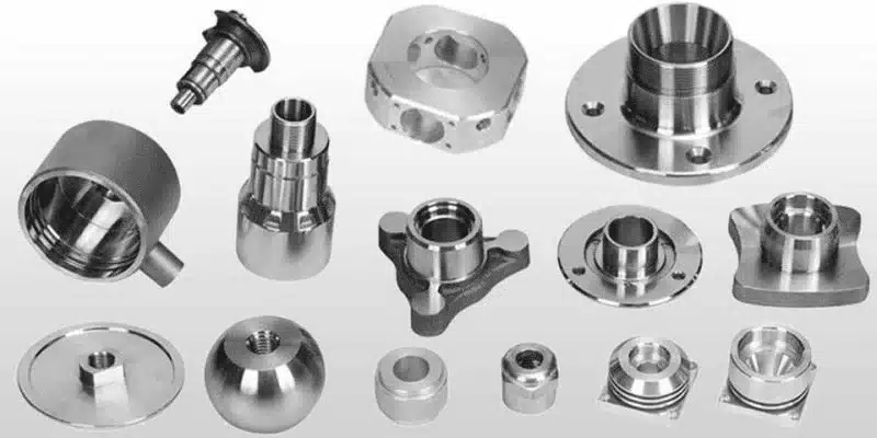
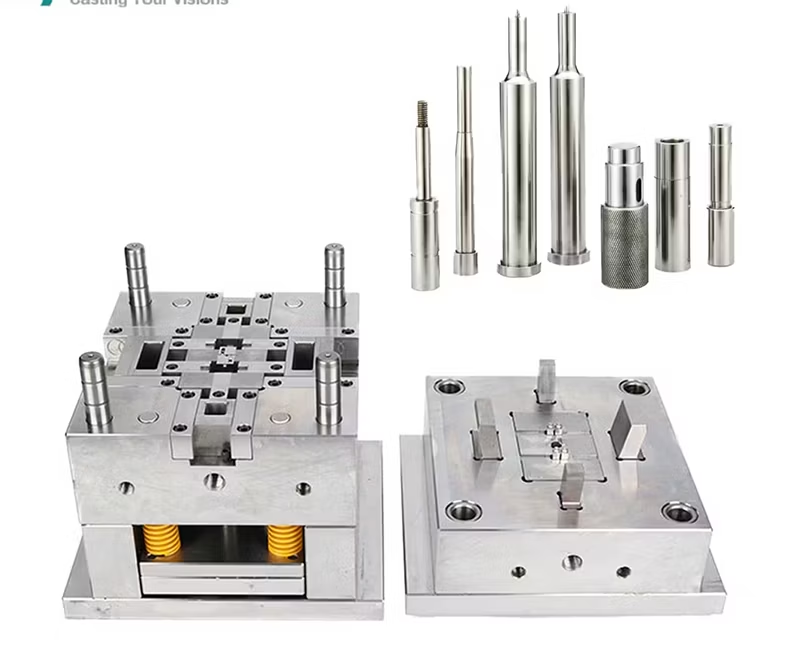
Realistic tolerance ranges for precision mold components vary, but standard benchmarks provide a starting point, always conditioned on specific contexts rather than universal guarantees. For core pins or ejectors, achievable tolerances often fall between ±0.005 mm and ±0.01 mm for diameters and lengths, sufficient for most injection molds to ensure smooth ejection and minimal flash. Smaller features, like micro-cavities in electronic housings, might push to ±0.003 mm under ideal conditions, but this depends on component type—cylindrical parts hold tighter than complex 3D contours due to easier fixturing.
Feature size plays a role too: larger bases might tolerate ±0.02 mm, while sub-millimeter details demand sub-0.005 mm to avoid part defects. Functionally, high-wear roles like sliders require stability over time, where initial tolerances must account for operational drift. From shop audits, I’ve learned these ranges aren’t static— they’re influenced by batch size and quality controls, emphasizing why blanket “micron accuracy” claims mislead.
How Machining Processes Influence Achievable Tolerances
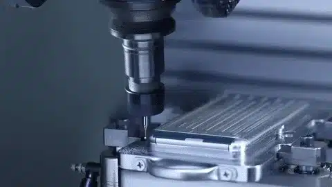
Machining processes set the foundation for tolerance control, with CNC milling and turning offering distinct strengths in repeatability that outpace one-off accuracy for mold production. CNC milling handles intricate geometries like mold inserts, achieving ±0.005 mm on contours through multi-axis paths, but stability hinges on spindle rigidity—vibration in extended cuts can widen variances to ±0.01 mm. Turning, ideal for rotational symmetry in pins, delivers concentricity under ±0.003 mm, yet thermal buildup from high speeds can induce expansion if coolant isn’t optimized.
Repeatability trumps single-part feats; a process capable of holding ±0.005 mm across 100 units matters more for mold assembly than a one-time hero piece. In evaluating overall system capability, partnering with providers skilled in Custom Parts Manufacturing ensures processes are tuned for consistent output, not just peak performance. For deeper process insights, exploring CNC machining for precision mold components highlights how selection impacts tolerance feasibility.
Material Behavior and Tolerance Stability
Material behavior profoundly affects tolerance stability, as properties like thermal expansion can shift dimensions post-machining, undermining initial accuracy. Steels with high coefficients (e.g., 11-13 µm/m/°C) might expand 0.01 mm over a 100 mm length with a 10°C rise, critical in heated molds where cores must maintain alignment. Internal stresses, released during heat treatment, can cause warping—I’ve seen H13 components distort by 0.02 mm if not stress-relieved beforehand, necessitating compensatory grinding.
Post-machining movement is another pitfall; softer alloys deform under clamping, while hardened ones resist but may crack. Selecting appropriate mold component materials is key to minimizing these effects, ensuring tolerances hold through assembly and use.
Functional Tolerances vs Cosmetic Precision
Distinguishing functional tolerances from cosmetic precision prevents over-engineering, as not all features demand equal rigor—prioritizing critical ones optimizes cost and performance. Functional-critical elements, like mating surfaces on sliders, require tight tolerances (±0.005 mm) for seamless operation and to prevent wear-induced failures, whereas non-critical areas, such as outer frames, can afford ±0.02 mm without impacting mold output.
Surface appearance often gets conflated with function; a polished finish might look precise but doesn’t guarantee dimensional stability if underlying tolerances drift. True precision lies in fit over aesthetics—focusing on surface finishing for precision mold components enhances durability without substituting for core tolerance control.
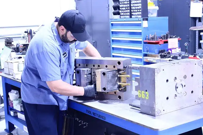
Inspection, Measurement, and Verification Limits
Inspection introduces its own limits, as measurement uncertainty can add ±0.001-0.002 mm variance depending on equipment calibration and operator skill. Coordinate Measuring Machines (CMMs) excel for complex geometries, probing to ±0.002 mm accuracy, but environmental factors like temperature fluctuations amplify errors— a 1°C change might skew readings by 0.005 mm on steel parts.
Verification isn’t foolproof; stylus wear or part fixturing can introduce biases, reminding us that inspection tolerances themselves must be factored in. Robust quality control in precision mold components protocols, including statistical sampling, help mitigate these, ensuring reported tolerances reflect real-world reliability.
How Tolerances Affect Injection Molding Performance
Tolerances directly govern injection molding performance, where even minor deviations in fit and alignment can cascade into defects like uneven fills or premature tool wear. Precise core-cavity alignments (±0.005 mm) ensure consistent part dimensions, reducing scrap from flash or warpage, while looser tolerances on non-mating features maintain efficiency without compromise.
Tolerance drift over cycles—due to thermal cycling or abrasion—amplifies issues, potentially dropping yields by 10-20% in high-volume runs. Understanding this interplay via injection molding quality guides specs that enhance repeatability and longevity.
Common Misconceptions About Tight Tolerance Mold Components
One widespread misconception is that tighter tolerances invariably boost performance, overlooking how they can induce brittleness or higher failure rates in dynamic molds. Another: assuming CNC machining guarantees micron accuracy across all runs, ignoring variables like tool deflection that erode consistency. Finally, believing inspection eliminates tolerance risk fails to account for ongoing drifts post-verification—real stability demands holistic design.
These myths persist from oversimplified specs; shop-floor truths reveal tolerances as balanced trade-offs, not escalations.
How OEMs Should Specify Tolerances Rationally
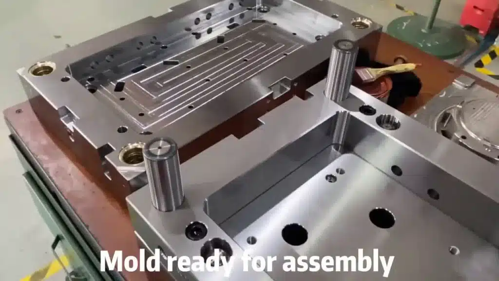
OEMs should anchor tolerance specs in function, classifying features as critical (e.g., alignments needing ±0.005 mm) versus non-critical (tolerable at ±0.02 mm) to avoid excess costs. Collaboration is essential—looping in manufacturers early refines designs, incorporating process limits for feasible outcomes.
This rational approach, honed from joint engineering sessions, prioritizes performance without waste, fostering durable molds.
Conclusion — Tolerance Is a System Decision
In conclusion, tolerance in precision mold component manufacturing emerges as a system-level decision, intertwining processes, materials, and inspections for balanced results. Pushing boundaries without context invites instability and expense; instead, align specs with functional demands for sustainable precision. Tolerance should be specified as part of a complete manufacturing system, not as an isolated performance target—it’s the pragmatic path to reliable tooling.