During injection molding tolerances are governed by the quality of tools and the stability of the process rather than by the machine accuracy itself. Although machined parts owe their accuracy to the machining capability of the machine, the tolerances of parts produced by injection molding is a complicated combination of factors that may change with each cycle. Such tight tolerances can only be possible when under controlled conditions, where the flow of materials, cooling rates and integrity of the mold are well controlled. Most OEMs believe that tolerances that are smaller always mean greater quality whereas in injection molding they can often result in greater variability and more cost. The tolerances in injection molding that are achievable are dependent on the accuracy of the tooling, the behaviour of the material and the consistency of the process rather than the nominal machine capability.
The knowledge of these dynamics is very important among the engineers and designers who want to have a reliable production of plastic components. Unrealistic specifications on tolerances without regard to the manufacturing reality may result in unnecessary costs, slow-downs in production and even field failures of the parts.
Why Tolerances in Injection Molding Differ From Machined Parts
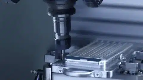
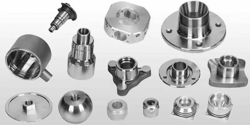
The tolerances in injection molding are more variable by nature than machining because it is a formative process. In subtractive manufacturing such as CNC machining, the material is carved out of a solid block, so the dimensions can be directly controlled by defining the movement of the tool and making repeatable cuts. The precision of the machine, typically to microns, is nearly one-to-one to the end product, provided it is set up correctly and with minimal deflection.
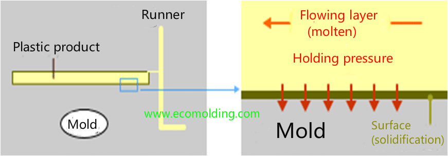
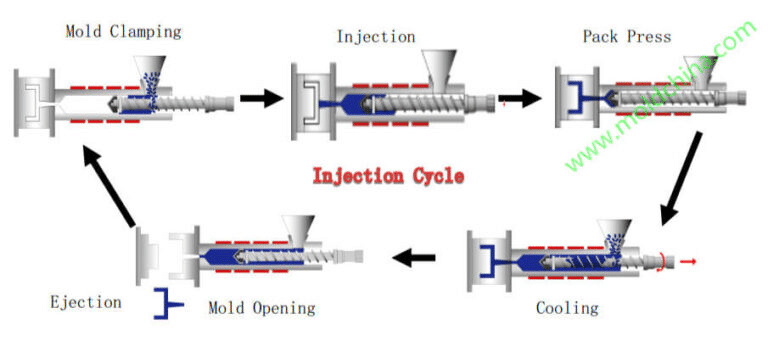
Conversely, injection molding is a formative process in which molten material of a plastic is forced into a mold cavity and solidified and ejected. This brings about cycle- based repeatability issues: every shot needs to repeat the last one under the same conditions, however, such factors as melt temperature, injection pressure, and cooling time may vary within a narrow range. Plastic behavior also increases the complexity; whereas, unlike metals, plastics are viscoelastic which is, they can creep on stress even at room temperature resulting in warpage or dimensional change as time passes.
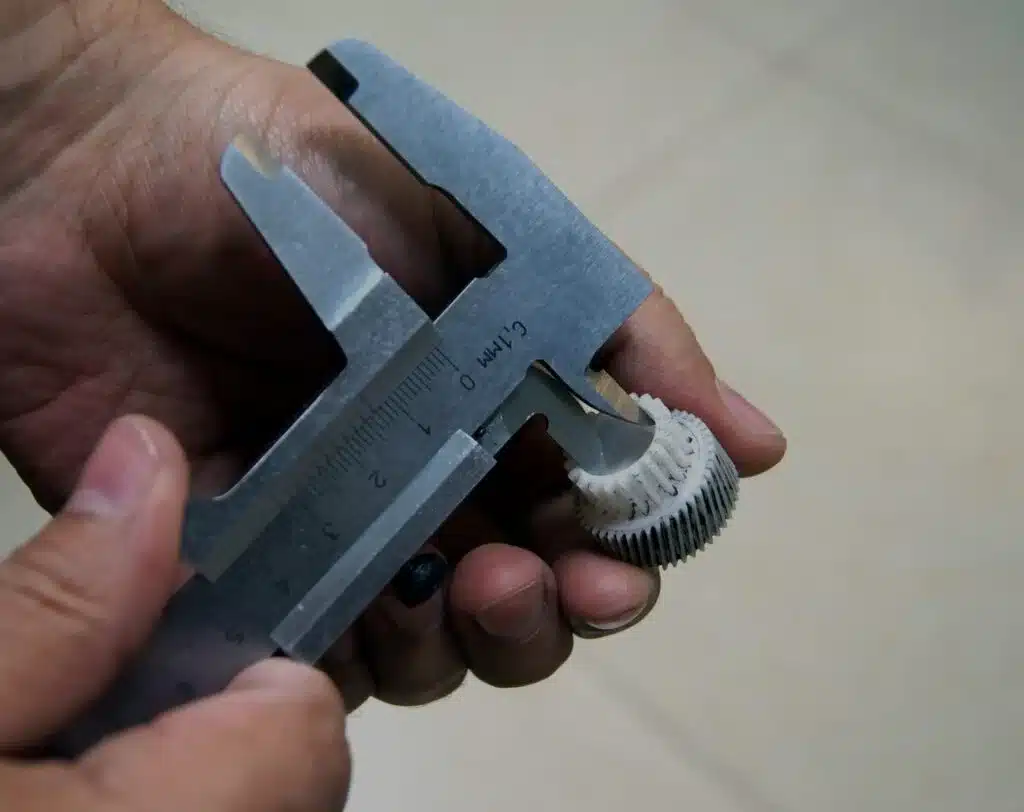
As an example, a machined metal bracket could be having a tolerance of: -0.01 +0.01 mm and this would be maintained all through its thousands of units since it is a deterministic process. However, in injection molding, to get the same dimensional accuracy of the plastic parts, one must consider the shrinkage that may be up to 0.5-2 per cent of the resin used. This is what renders injection molding tolerances system-driven, based on the whole production ecosystem and not the press itself. To prevent applying machining expectations to molded parts, the engineers need to identify these differences as it may lead to unrealistic designs and increased rejections.
Nominal Tolerance vs Functional Tolerance in Plastic Parts
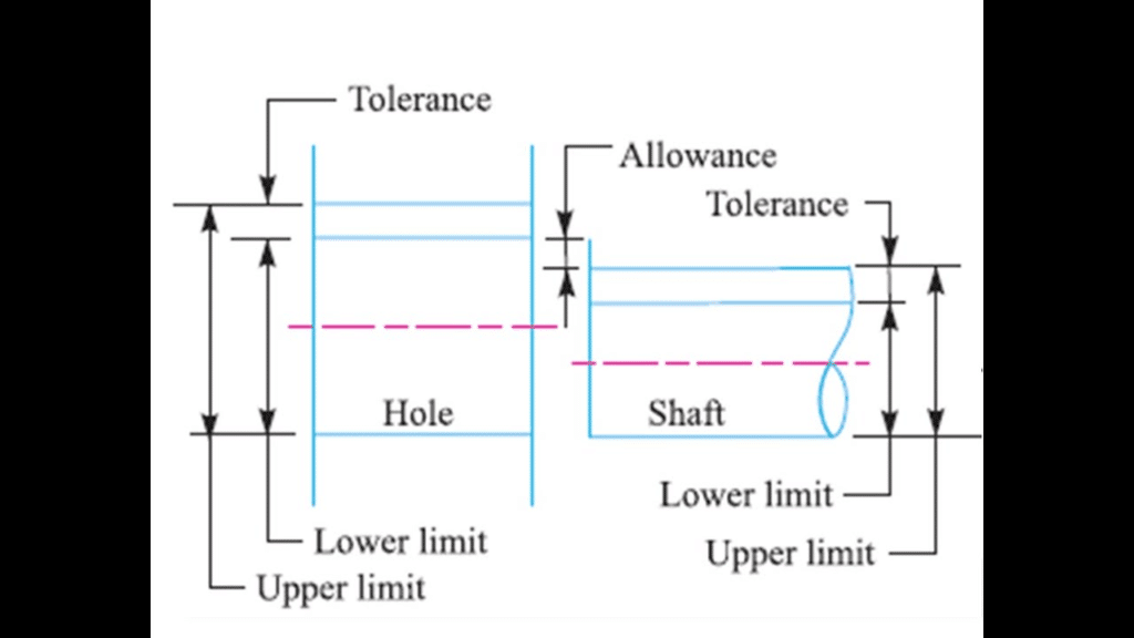
Nominal tolerances reflect what the drawing would appear like ideally, whereas functional tolerances consider what is really important to the performance of parts and assembly. The indicated limits of nominal features such as hole diameter or wall thickness are the so-called nominal tolerances, which are commonly based on standard charts or CAD models and the specifications do not really take into account the end-use requirements. They give one a starting point which may be misleading when not matched with part functionality in its use.
Functional tolerances, though, consider more the dimensions that are important to fit, form, and function – like mating surfaces or load-bearing areas – and not so important on non-critical ones. The method is necessary in injection molding since excessive tightening of nominal values throughout the board can enhance fluctuations brought about by inconsistencies in flow of materials or thermal growth.
As a real world example, the overall length tolerance in an automotive connector housing may be artificially set to be within a nominal range of 0.200 mm with a functional tolerance being smaller at 0.050 mm to allow electrical connectivity. Defining standardized nominal tolerances may cause unwarranted adjustments of tooling and with no benefit on the assembly. Another example is medical device enclosures where the injecting moldings tolerances are functional to guarantee the integrity of the seal in terms of sterility, even though the aesthetic appearance may be slightly different. Tolerance planning of parts injected in plastics is a strategic process and not a blanket approach when it comes to designers having the ability to provide reliability in their performance and reducing the production risks by focusing on functional tolerances instead of blanket tolerances.
The Role of Tooling Quality in Tolerance Control
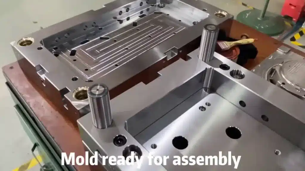
The basis of consistency in tolerances in injection molding is high-quality tooling since slight defects on the mold can be transmitted through thousands of injections. Accuracy of mold cavities directly relates to the shape of the part the first, so CNC-machined cavities that are finished to a better than 0.8 m surface finish can be made to hold smaller dimensions, but a failure in core-cavity registration may result in flash or wavy walls.
Balance of cooling is also crucial- imbalanced cooling paths may cause unequal contraction, distortion of components off-spec- P20 hardened or even hardened H13 steel is a better material as it does not wear easily like softer alloys, but remains dimensionally stable through longer production. Tool life is almost unavoidable, particularly in large-volume manufacturing, where fillers within the resin are abrasive, enhancing the erosion rate, eventually expanding the tolerances of the original ±0.05 mm to ±0.15 mm after 500,000 hits.
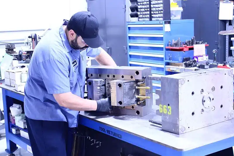
It is here that collaboration with established suppliers of would be involved. precision injection molding services is necessary, since they are able to create molds with characteristics such as conformal cooling to improve consistency. In practice, I have seen examples where the transition of a simple two-plate mold to a hot-runner system resulted in tolerance control being 30% better, and the scrap rate was reduced due to generation of thermal imbalance. Finally, the costly investment in high quality tooling is compensated in the long term in terms of dimensional accuracy.
Material Shrinkage and Thermal Behavior
The initial cause of dimensional variability in injection molded components is material shrinkage which differs dramatically between resins and has a direct influence on tolerances. Amorphous plastics such as ABS contract at a constant rate of approximately 0.5-0.7% whereas semi-crystalline such as nylon may contract at an anisotropic rate of up to 2% based on crystallization of the material in the cooling process.
This is aggravated by fiber reinforcement and fillers; glass-filled compounds can reduce total shrinkage to 0.2-0.5 percent but introduce orientation effects, i.e. the size in the direction of flow is not equal to that perpendicular to it. This may cause oval holes or bowed surfaces when this is not expected when designing molds.
These problems are aggravated by an increase in temperature- humidity in the air has penetrated the hygroscopic resin such as PA6, leading to post-mold swelling, change in dimensions by 0.1-0.3%. Melt and mold temperatures should be tightly regulated by processors; a 10 o C variation can cause shrinkage to change by 0.1 percent, and put components outside the tolerance range.
For optimal results, choosing the right plastic for injection molding is key,as it matches material properties with design requirements. In electronics enclosures, such as those of low-shrinkage PC/ABS blends, dimensional accuracy of plastic parts is more than that of straight polycarbonate in wet applications. These behaviors of injection molded parts should be considered in tolerance planning by the engineers to eliminate unexpected behavior during validation.
Process Stability as a Requirement for Tight Tolerances
The tight tolerances cannot be maintained without process stability because even sophisticated tooling is unable to deliver the desired results without the ability to maintain consistency in the cycle parameters. A constant process window is used to keep the variables such as injection speed, pack pressure and cooling time within narrow ranges to reduce the differences that occur between shots which might be as large as 0.05 mm of the critical dimensions.
Cycle consistency has a direct relationship with dimensional repeatability; short, runs may be easy to hit, however, when it comes to mass production, there will be a drift in behavior of the machine due to wear or changes in the environment. This is the reason why short-term capability (CpK >1.33 when first samples) does not ensure long-term tolerance control- changes in the resin viscosity or clamp tonnage with time can deteriorate the performance.
In my Practice, processing the de-coupling of the fill, pack, and hold stages, have allowed the stabilization of processes to hold -.03 mm on functional features. Understanding the injection molding process in depth allows for proactive adjustments, like real-time monitoring with cavity pressure sensors, to catch deviations early. Without this stability, pursuing aggressive tolerances risks inconsistent quality and higher costs.
How Tolerance Decisions Affect Cost and Production Risk
Excessively restrictive tolerance requirements increase the cost exponentially and risk to production, but with little, or no, equivalent direct payback to part functionality. Every step of greater accuracy – e.g. ±0.1 mm to ±0.05 mm – may need better tooling steel, a faster cooling system or a slower cycle time, a 20-50% increase in the cost of the mould and a decrease in throughput.
Tighter specs are common pitfalls, increased scrap and rework increases the effects of small process variations, and rejection rates go up to 1% or more. Not only does this waste material, but it holds up the machines as well, which delay deliveries.
It is important to balance tolerances needs with production reality, functional tolerances in injection molding mean that the specs on non-critical features can be slack in order to maximize cost-efficiency. To illustrate, in consumer electronics, the saving of 15 percent of tooling in a single project by relaxing cosmetic tolerances did not result in any loss of assembly fit. Misguided decisions will trickle down to supply chain interruption and this explains why informed tolerance planning of injection molded parts is necessary.
How OEMs Should Specify Tolerances for Injection Molded Parts
To provide manufacturability and reliability, OEMs should specify tolerances based on emphasis on functional dimensions rather than similar nominal values. Begin with the creation of a list of critical-to-function (CTF) features through Geometric Dimensioning and Tolerancing (GD&T), defining datums and controls through form, orientation and position more efficiently than the simple plus/minus notations.
Utilizing GD&T in the correct manner, e.g., a hole being at true position, helps to minimize ambiguity and ensure that manufacturers can put efforts in the areas that are important. Close coordination with design and manufacturing teams is essential at the beginning of the process to provide insights into problems that might arise during the process such as sink marks on flatness.
Incorporating quality control in precision mold components at the very beginning, by using techniques such as CMM inspection, assures that specs are realistic. This strategy has been used in automotive to define ±0.1 mm on surfaces used to mate and permitting ±0.3 mm in other parts, reducing time to do validation by 25%. At the same time by basing specifications on engineering realities, OEMs create an efficient production that is not at the expense of performance.
Conclusion — Tolerances Must Reflect Manufacturing Reality
Injection molding tolerances are essentially a design issue which should be consistent with the tooling, material and process capabilities to achieve consistent output. Insisting on the absolute accuracy out of context does not take into account the variables inherent in plastic forming, which may cause inefficient results. Rather, success stems out of realistic specifications in terms of functional requirements, which are backed by quality tooling and stable operations.
Collaboration between OEMs and manufacturers is needed- early exchange of insights may help in improving designs to have a better tolerance and reduced risks. Ultimately, the ability to create injection molded plastic parts with effective tolerances can be achieved through a judicious consideration of constraints and opportunities, and so the parts can work as designed without being overly complicated.