Injection molding tooling lead time has been misconstrued as a time-out race within the machining shop. The truth, however, is much different: there is no meaning behind tooling lead time reduction except to increase the machining speeds and committed resources to the production. Rather, most lead time problems are established long before any production is started and have a foundation in the design of the molds when a decision is made on the course of the entire project. The prevalent myth regarding tooling lead time is that it is more of a manufacturing speed problem, and indeed, referencing early mold design choices that are more of a determinant of design complexity, manufacturability, and iterations.
Mold design determines the upper and lower limit of the possible tooling lead time. The lead time of tooling is more of design rather than a machining speed issue. Knowledge of the influence of mold design on tooling lead time helps OEMs and engineers to manage expectations and reduce risks more effectively. The experience of this article is based on our years of experience in the management of complex tooling projects at some of which we have personally experienced the effects of unfinished designs being transferred to the stages of machining, assembly, and trials.
Why Mold Design Is the Primary Driver of Tooling Lead Time
The mold design is the starting point of all other stages in the production of a tool, and thus, it is the greatest indicator of the total lead time. Once the designs are well defined, comprehensive and optimized initial onset, the overall process becomes much predictable. On the other hand, uncertain or changing designs add uncertainties that roll over to production, which can add weeks or months to the schedule.
The connection between clarity in design and predictability in the schedule is simple, clearer mold design would minimize questions in the fabrication process that consume time. In a project, where part geometry is completely defined with tolerances, tool material and tooling layouts are defined in advance, we have seen tooling schedules shrink by as much as 20-30 percent relative to projects whose requirements were vague. The stable designs also minimize the downstream uncertainty by enabling the correct quoting, material acquisition as well as planning of the processes without interruption.
In the engineering context, design instability, e.g. undefined parting lines, or unresolved undercuts, causes teams to wait at a critical point until they can get clarifications that would have been clarified at an earlier stage. That is why tooling engineers with experience underline the need to freeze the designs as soon as possible; otherwise, the injection mold design schedule may be exposed to unnecessary delays. To fully support this field, mold design and tooling services, which integrate these principles to enhance project efficiency.
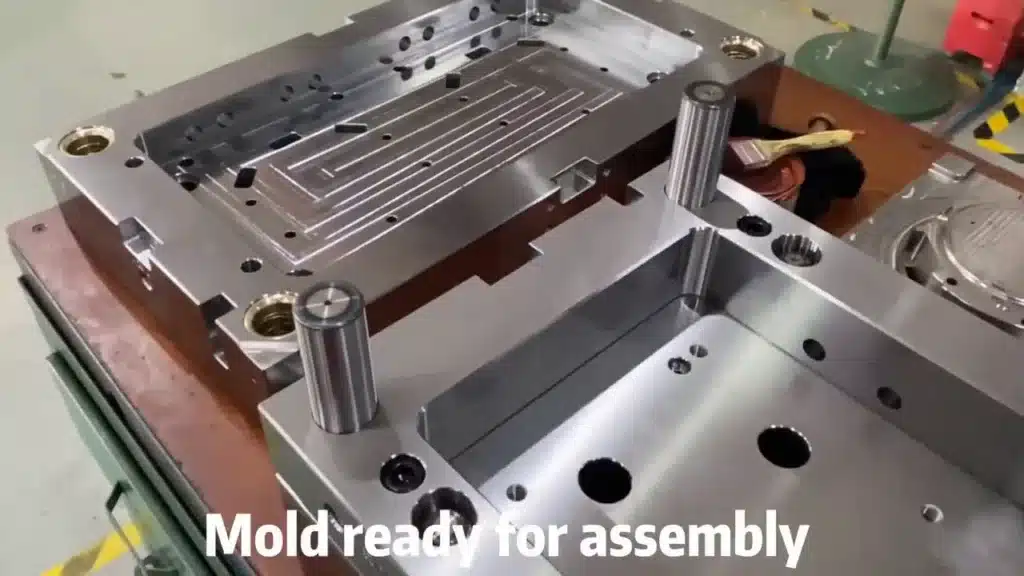
Understanding Typical Mold Making Lead Time Structure
The lead time of tooling is a systematic process that has a series of steps, each of which requires another step and the overall result depends highly on the quality of the original mold design. Splitting it up lets one see the presence of design choices that are made at every step, starting with conceptualization and up to its final confirmation.
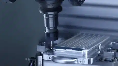
An average mold making process involves the finalization of design, purchase of material, machining, assembly, polishing, and tests. The design choices affect every step defining the complexity and resources needed. As an illustration, incomplete specifications in the design phase may slow down approvals and intricate features may require more programming and set up time in machining.
The following table that describes the stages and dependencies would be useful to show the factors of tooling lead time in a more illustrative way:
| Tooling Stage | Design Dependency | Delay Risk |
| Design finalization | Very high | High |
| Machining | Medium | Medium |
| Assembly | Medium | Medium |
| Trial | High | High |
This discontinuity highlights the reason behind the highest percentage of schedule overruns by mold design delays. To discuss timelines in more detail, visit our guide to typical structure of the lead time typical mold making lead time structure, which provides benchmarks based on real projects.
Key Stages in Detail
Design Finalization
This is the stage in which the area of most critical intersection lies in mold design and tooling schedule. High dependency is due to the fact that any uncertainty in this case e.g. indefiniteness of the tolerances or gating strategies will stop the flow until the issue is addressed.
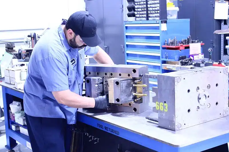
Machining and Assembly
Although they are execution-oriented, design information such as the number of cavities, or the positioning of the ejectors have direct effects on the cycle times and the probability of error.
Trials and Validation
Trials reveal design flaws making what is supposed to be an afferting step a rework loop in case the design is not robust.
Design Decisions That Commonly Extend Tooling Lead Time
Some tradeoffs in the design of the mold will always bring complexities that will increase the tooling time, but not always obvious at the conceptual stage. Parting lines with complex geometries e.g. need extra engineering time to make sure that the separation of the molds is adequate and it does not flash or have defects, which alone takes days to be designed.
The other common culprit is excess undercuts and side actions; these attributes require specialized machining such as lifters or sliders, which not only add to the length of machining, but also add to the complexity of assembly. Stringent and unneeded tolerances drive the manufacturing precision to the limit, requiring slower feeds and numerous inspections that add to the schedule.
These problems are compounded by late design changes, since most changes made during the design process need to be undone reprogrammed CNC paths or resorted to rearranging the materials. Projects that involve high revisions are associated with twice the tooling schedule risk in our case, with automotive and electronics tooling projects.
It is important to understand these decisions in mold design decisions and manufacturing impact to reduce the delays and maximize the costs.
Specific Examples of Problematic Decisions
Complex Parting Lines
This can add 1-2 weeks to design and machining unless simplified in the initial stages.
Undercuts and Side Actions
They demand bespoke parts, increasing assembly risk with regard to delay.
Overly Tight Tolerances
Precision unnecessary delays all stages proportionality less greatly.
How Design Issues Lead to Trial Delays and Rework
The flaws in design are common when it comes to mold trials and what would otherwise be a basic validation process turns into prolonged periods of modifications and testing. This is a critical stage since experiments undertaken through trials are a simulated production stage and therefore, unbalance or flaws are realized, which may not be found during theoretical review.
Design completeness and design trial iterations are related directly: incomplete design results in an increase in cycles, since problems such as uneven cooling or bad venting require physical adjustments. In the example, the design does not provide venting; thus, in tests, burn marks are formed necessitating the addition of more venting and even new inserts.
To emphasize pitfalls, the following table is a graph where design problems are correlated with their outcomes in the trial:
| Design Issue | Trial Outcome | Schedule Impact |
| Cooling imbalance | Warpage | Delay |
| Ejection design flaw | Sticking | Rework |
| Venting omission | Burn marks | Additional trials |
These mold design issues causing trial delays problems with the design of the mold that result in a delay of the trial are sometimes due to the neglected principles of DFM, which require in-depth analysis at the preliminary stage.
Root Causes in Trials
Cooling System Oversights
The asymmetrical cooling causes the variations in dimensions, which necessitates schedule extensions.
Ejection and Venting Flaws
They lead to part defects, which require a rework that eliminates any previous time savings.
Why Faster Manufacturing Cannot Fix Poor Mold Design
Trying to speed up production as a result of faulty designs is a pointless tactic that tends to backfire and the expenses are increased with additional delay. The boundaries of accelerating machining are clear: even with the high-end CNC equipment, bad designs create unproductive results such as a high frequency of tool changes, or poor paths, which cannot be completely counteracted by speed.
Furthermore, any perceived speed benefits are bound to be lost in case of rework. When a design flaw is realized after machining, e.g., an incorrectly matched cavity, then the teams have to take the parts to pieces and re-manufacture, which cancels the importance of hurry in previous phases. Out of dozens of tooling programs under management, it is evident that fabrication hurried on unsound designs exacerbates the errors and a small problem erupts to become a big one.
Limitations of Speed-Focused Approaches
Inherent Process Constraints
The machine speed is limited by material characteristics and the life of the tool, irrespective of the equipment.
Rework Cycles
The design mistakes generate cycles that take longer time than what would be saved by acceleration.
Design Discipline as the Most Effective Way to Control Lead Time
The surest way to ensure the control and reduction of quality of tooling lead times is the strict application of design discipline during the initial design phase. This begins with extensive Design for Manufacturability (DFM) audits where likely problems are found and solved before a commitment is made to manufacture.
The time of design freeze is important; a deadline on when the design can be changed will avoid scope creep that will upset schedules. Linked to this is the importance of communication of clear functional intent to make sure that all the stakeholders are aware of the performance requirements to prevent misunderstandings.
Theoretically, projects that have high DFM protocols have reduced tooling schedule risk because early simulations uncover issues that would otherwise postpone trials.
Building Discipline
DFM Reviews
Engage cross-functional teams to agree on possibility.
Freeze Protocols
Establish strict deadlines of revision to keep the momentum going.
Common Misunderstandings About Design and Tooling Lead Time
The relationship between tooling lead time and mold design is also subject to many misunderstanding, and therefore, teams do not allocate efforts and resources correctly. The most common assumption is that we will correct design problems later because it does not take into account the spread of delays across interdependent phases by late changes.
Another one is that speed of machining defines delivery ignoring the role of design in defining the minimum efficiency. Lastly, the argument that trial delays are inevitable rejects the fact that the proactive design can reduce the number of iterations.
These issues would have to be dealt with by shifting to the perception of lead time as a whole, which is determined mostly by upstream choices.
Debunking Key Myths
Fixing Issues Later
This method is unrealistic in terms of cost of rework.
Speed Over Design
Foundational flaws cannot be countered by machining.
How OEMs Should Manage Mold Design to Protect Tooling Schedules
One of the ways through which OEMs can protect tooling schedules is to practice proactive management that emphasizes on design preparedness and control. This starts with designing thoroughly, comparing the design to the manufacturing standards to indicate gaps at an early stage.
Control discipline is also critical, which involves formal procedures used in approving change in order to avoid ad-hoc change. Risk identification at early stages, e.g., using the FMEA (Failure Mode and Effects Analysis) tool, is useful to predict and avoid possible delays.
Concentrating on them, OEMs decrease the chances of a delay in the design of molds and are more predictive.
Practical Management Strategies
Readiness Assessments
Reviews based on a checklist make sure that designs are ready to be used in production.
Change Controls
Approvals are recorded and therefore stable.
Risk Identification
Preventive analyses identify weaknesses early enough before they affect timelines.
Conclusion — Tooling Lead Time Is Designed, Not Rushed
In short, tooling lead time is pre-decided way before machining and strict discipline in mold design is the best method of making sure delivery can be predicted. Ensuring that the design is clear, stable, and thoroughly reviewed, teams will not fall into the traps of adding more time and more money to the project. This will create a sense of reliability instead of haste which will ensure projects are completed as expected without any cases of wasteful risks. Finally, the discussion of the effects of mold design in relation to tooling lead time provides an OEM with the knowledge to make informed decisions that are consistent with the actual manufacturing realities.