
Introduction
The commercial sector relies on injection molding materials as one of its most flexible and ubiquitous manufacturing methods. The manufacturing approach enables the economical creation of complex plastic parts through exact replication on a large scale basis. The production of optimal results depends on complete mastery of appropriate design methods plastic flow. The design method affects both manufacturing capabilities of parts and drives efficiency levels during production run while determining final part quality as well as manufacturing expenses, including the placement of injection molding gates . Engineers and designers need this complete guidance to develop parts which fulfill their operational needs and maintain cost-effectiveness for manufacturing.
The plastic material undergoes plastic injection molding by melting it before the process pushes it into prepared mold cavities to solidify as the desired final part. The process exists as a seemingly easy method yet its demands complex linkages between material properties and part shape constraints and processing setting specifications during the injection molding cycle . When designers fail to consider important design factors their work results in product defects alongside manufacturing delays plus higher production expenses and inferior component performance.
The piece presents whole information about injection molding design principles which extend from fundamentals to state-of-the-art practices plastic resin. These guidelines help engineers to reach optimal manufacturability results while shortening their development cycles for superior product quality outcomes and reducing tooling costs .
Understanding Material Selection

Thermoplastic Properties and Selection Criteria
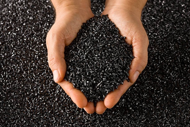
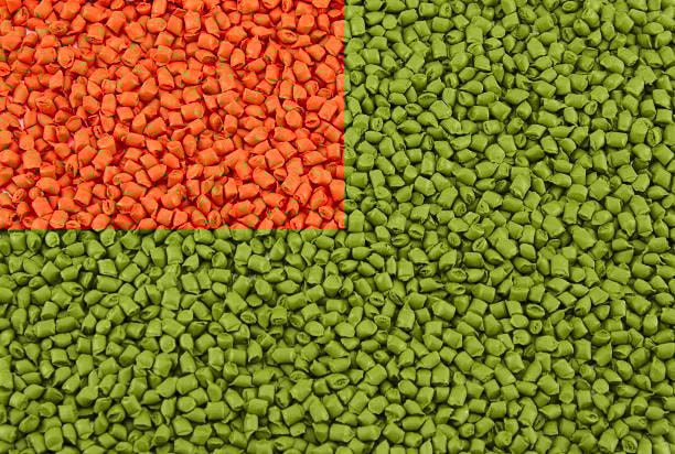
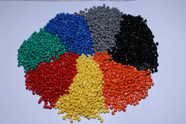
The selection of proper materials constitutes the core aspect for manufacturing plastic parts in designing successful injection molding applications. Different thermoplastics demonstrate distinct attributes such as their flow behavior while melting as well as their shrinkage behavior and their mechanical performance and thermal properties and their resistance to chemicals. The main materials used for injection molding consist of polyethylene (PE) together with polypropylene (PP) as well as polystyrene (PS) alongside acrylonitrile butadiene styrene (ABS) and polycarbonate (PC) and polyamide (nylon). Injecting materials should depend on these factors for selection:
- Mechanical requirements: tensile strength, impact resistance, flexibility
- Environmental conditions: temperature range, UV exposure, chemical contact
- Regulatory compliance: food contact, medical applications, flame retardancy
- The producer needs to consider processing aspects which include mold temperature and cycle time alongside melt temperature.
- The processing economy relies on two primary aspects which consist of material expense and equipment productivity.
The data sheets for materials supply essential processing information by specifying melt and mold temperature recommendations and drying procedures together with injection pressure specifications. Knowledge of these parameters at the beginning of design work stops unnecessary expenses from occurring during later stages.
Material Flow Characteristics
Mechanical uniformity during part filling depends heavily on flow behavior in plastic materials. Products that demonstrate higher melt flow indices create better section flow due to their easy-going composition yet show reduced mechanical strength levels with the addition of glass fibers . Safer processing requires materials with low MFI although these substances provide inferior structural strength.
Flow simulation software helps designers avoid future tooling problems during part creation when used to evaluate structures with both diverse wall thickness arrangements and intricate pathways. The flow simulation technique allows designers to find potential short-shot zones and air-trapped or welded areas in advance so they can take preventive actions.
Wall Thickness Considerations
Maintaining Uniform Wall Thickness
Engineers must focus on designing injection molded parts with rounded corners and avoiding sharp corners while maintaining evenly distributed wall width since this remains among the crucial fundamental design principles. The length of time until cooling proceeds between different wall thickness areas leads to problems such as component warping and subsurface deformation as well as stress buildup. Recommended practices include:
- Choose initial wall thickness by considering part needs together with material characteristics.
- The thickness of parts should remain within 15% of the nominal value whenever layout permits.
- The implementation of thickness transition requires using slow transition bands which follow the 3:1 ratio rule
- Thick wall sections should be avoided because they slow down cooling time excessively or generate visible marks known as sink marks.
- Use design ribs between 50% to 70% of wall thickness to stop sink mark formation
- The hollowing technique helps keep thick sections uniform when used with core-outs.
Industrial sector needs apply thickness measurements between 0.5mm and 4mm based on their material choices and operational requirements. Custom application needs require analysis of processing limitations when using walls with dimensions other than the standard range.
Minimum and Maximum Thickness Guidelines

The lowest feasible wall thickness depends on material flow properties and the amount of available injection pressure. The attempt to finish small sections leads to unwanted problems with shots or pressures from injection and damage from high shear rates due to material breakdown. Maximum part thickness matters foremost for heat dissipation duration and dimensional precision both within the product as well as its total volume.
Material-specific thickness guidelines can be applied using an injection molding machine :
- PE/PP: 0.8-3.0mm
- ABS: 1.2-3.5mm
- PC: 1.0-4.0mm
- PA (Nylon): 0.8-3.0mm
- POM (Acetal): 0.8-3.0mm
Draft Angles and Part Removal
Draft Angle Fundamentals
Moldable parts require draft angles because these subtle slopes on mold surfaces aid in pushing them out during the unclamping process. Inadequate draft leads to parts getting stuck inside the mold cavity which might damage the parts or force the mold to use excessive ejecting power. Draft angle requirements depend on:
- Textured surfaces need greater draft than smooth surfaces because of their design.
- Material shrinkage characteristics
- Depth of the feature
- Surface finish requirements
- Ejection system design
General draft angle recommendations:
- Professional designers should grant all smooth surfaces at least 0.5° to 1° draft angle per each side.
- The minimum draft angle specification for textured surfaces should be between 1.5° to 3° per side with 1° more draft angle added for each depth of 0.025mm in texture.
- The draft requirement for deep ribs or bosses extends to 3-5° angles.
- Categories with external features need lower draft allowances compared to internal ones.
Draft angles implemented correctly enable both efficient component ejection and shorter production cycles and longer tool lifetime through decreased core and cavity surface friction.
Undercuts and Side Actions
A mold ejects parts by direct ejection only when features known as undercuts do not exist. The list of elements requiring draft includes snap fits and threads along with features that run perpendicular to the parting line and surface textures. Managing undercuts requires either:
- The three types of side action tools include slides, lifters and cam actions.
- Hand-loaded inserts
- Collapsible cores
- Unscrewing mechanisms for threads
Every additional method implements more complexities and higher cost for the mold. Redesigning features for undercut removal decreases both tooling expenditures and maintenance requirements whenever design modifications are possible. For example:
- Joint snap fit parts should be placed at the parting line.
- The design should incorporate self-tapping threads instead of using molded threads.
- Holes within the mold should be oriented in the same direction as the mold opening path.
- The mold features should appear in an up-down direction instead of from side to side.
Tooling complexity and cost decreases when different features utilize the same side action to bypass undercuts which are unavoidable.
Ribs, Bosses, and Structural Features
Rib Design Guidelines
Structural ribs support the design and make thin wall sections possible which saves materials and speeds up production. The right rib formation must adhere to these rules:
- These ribs should have a thickness equal to between half and two-thirds of the wall area next to them to avoid sinking.
- The highest position of a rib should be three times thinner than the neighboring wall to keep sections from distorting.
- Place spacers at least two to three times the rib thickness apart for good preparation of material flow.
- Base radius should measure at least 25% of the thickness level in the adjacent wall plate to decrease stress at attachment points.
- The surface angle needs at least 0.5 degrees of draft toward each side (more for textured areas)
Placing ribs in either concentric circles or cross patterns provides best support and helps material flow move freely. Keep ribs spaced evenly on the walls instead of putting two ribs opposite each other in parallel because parallel ribs make the parts cool too slowly.
Boss Design Guidelines
Boss installation areas serve as connection points for different parts. Proper boss design includes:
- The boss outside edge measures between two and two and a half times wider than the hole size
- Wall thickness: 60% of the nominal wall thickness
- Base radius should be equal to the wall thickness next to it.
- Add supporting ribs between main walls to make the part stronger.
- The part mold design needs at least 0.5-degree slope in each direction inside and outside the part.
- When possible drill holes completely through the part material to reduce thickness
Give threaded inserts enough space for them to stay supported on the base material. Designers usually suggest an outer wall of at least 0.5 insert diameter thickness. To make self-tapping screws function properly with liquid silicone rubber, you should drill pilot holes per manufacturer specs given by the screw manufacturer.
Gating and Runner Systems
Gate Types and Placement
Part production efficiency takes direction from how designers arrange and position the gates. Common gate types include:
- Pin gates offer small openends for decorative product parts.
- The edge section of the part features rectangular gate openings.
- Silent gates rest under the molding line for automatic part cutting during production.
- Thin fan gates fill large surface areas evenly during injection molding.
- The use of stock from the hot runner system produces direct gates.
- Circle-shaped gates serve well for making round components.
Gate location considerations:
- Place gate entrances in the part areas with maximum thickness to achieve good filler action.
- Put the water flow path through thicker to thinner part sections.
- Install gates at positions that allow proper weld line development in non-visible areas
- Decide how to see and trim the gates
- Keep the gate a suitable distance from exact dimensions of the part.
- Place the gate away from parts where stress resides or surface looks appear
A balanced runner system helps distribute melted plastic evenly to all cavities of a mold. A fishbone natural gating system fills cavities more evenly than artificial systems.
Avoiding Common Gating Problems
Faulty gates create different quality problems including cosmetic defects:
- Material shooting out from cavities during filling produces cosmetic damage and weak spots in the parts.
- The part section congeals earlier than other parts because the metal has not yet filled the entire mold.
- The joining points between material fronts after making their way around barriers mark fragile areas in the product design.
- Trapped air forms empty cavities and damage to the part
- Stressed colors appear at gate positions when slow filling material contracts against these positions.
- The ends of trimmed gates leave noticeable flaws and marks in the final part surface.
To minimize these issues:
- Adjust the gate size according to material type and part quantity
- Place the gates in specific locations to direct material smoothly into the cavity space.
- Install effective vents to help air release during production
- Use a systematic valve opening system for challenging component production
- Our simulation tool helps us find and solve mold flow problems ahead of time.
Managing Weld Lines and Flow Patterns

Weld Line Formation and Mitigation
Two or more plastic streams merging during molding will create cosa weld line that connects their paths, impacting the cosmetic appearance of the product . These specific areas show structural imperfections because of their mechanical failure risk and surface defects. Weld lines commonly occur:
- Around holes or cores
- In parts with multiple gates
- The material must pass through restricted passages in these parts.
- The thinner regions receive material supply from thicker areas on their base.
To reduce weld line problems manufacturers use different methods such as:
- The relocation of gate openings changes material movement to improve filling process results
- Raising the local part thickness in weld line locations
- By increasing the temperature of molten material during injection and molding cycles the polymer bonds perform better.
- Higher injection speed and stronger pressure pushes the material parts to create better connections.
- We use special marks to show the material where and how to flow during production.
- Instead of using regular materials try materials that resist weld line failures better
- Fitting surface textures over weld lines helps reduce their visual appearance
Process simulation helps businesses identify weld lines earlier to make necessary design changes before building molds.
Flow Leaders and Restrictors
Special parts within the cavity system manage material flow into its desired pattern. Flow leaders are enlarged areas that assist flow movement whereas restrictors are narrower sections that slow down flow movement in designated directions. Strategic implementation helps:
- Balance fill patterns
- Control weld line locations
- Prevent air traps
- Use cooling techniques to keep the mold materials from bending unevenly.
- Control the pressure flow through the entire part design
Flow leaders generally have 15% to 25% greater wall thickness than regular cavities while restrictors are built with 10% to 20% less material than other parts. The design team should ensure that proper wall thickness is maintained while building up wall thickness changes slowly rather than making sudden step changes.
Cooling and Shrinkage Management
Designing for Uniform Cooling
Equal part cooling maintains its shape by preventing unintended distortion. Design considerations include:
- Maintaining consistent wall thickness
- We distribute cooling evenly between the part cores and cavities.
- Create enough space in the part for heat to escape properly.
- The part should have equal cooling airflow distribution throughout its design.
- We need new cooling techniques that work well with special component shapes
- Conformal cooling channels
- Baffle systems
- Bubbler cooling
- Beryllium copper inserts help dissipate high heat from specific product zones effectively
The cooling system must reflect unique material responses to cooling plus material shrinkage levels. Advanced materials need better cooling systems to reach the best processing times as well as part results.
Shrinkage Compensation Techniques

At handling temperature all thermoplastic materials will naturally shrink during their transition from processing heat to room temperature. Shrinkage rates vary by:
- Thermostats made up of crystals generally shrink at higher rates than amorphous materials.
- The outcome of parts depends on the temperatures used during processing along with the applied pressure and thermal measures.
- Part geometry (wall thickness, reinforcement structure)
- The part shrinks more strongly in the direction of the flow process rather than across it.
Typical linear shrinkage ranges:
- PE/PP: 1.5-2.5%
- PS: 0.4-0.7%
- ABS: 0.4-0.9%
- PC: 0.5-0.7%
- PA (Nylon): 0.8-2.0%
- POM (Acetal): 1.8-3.0%
- Glass-filled materials contract between 0.2 and 0.8 percent depending on amount of fiber addition
You need to adjust mold dimensions before they contract when making products. Modern CAD platforms let users include shrinkage factors as design parameters in mold development for the injection molding process . In advanced designs the shrinkage percentage varies across part segments mainly due to their distinct shapes and fluid movements.
Parting Line and Ejection System Design
Parting Line Selection Criteria
The parting line shows the point where mold halves come together and forms a visible mark on the completed part. Optimal parting line selection considers:
- Select ejection plane directions that result in straight part movement
- Organize the parting line to hide in unimportant areas of the product
- Use specific spots on the mold tool to manage where flash will most likely appear
- Mold complexity: Minimize the need for side actions
- Adequate venting should be placed at both ends of material movement throughout the process.
- Michael selects mold areas that allow parts to exit without mix-up between mold halves
Special parts need non-level or multiple parting lines that fit their geometric shapes and hide away from visible surfaces.
Ejector Pin Placement and Design
After opening the mold ejector pins bring the part off the core. Proper ejector system design includes considerations for manually trimmed gates :
- Place ejectors on parts that stay firm under the ejection forces
- Add enough ejection pins across the part surface to balance pressing forces
- Choose pins with the suitable dimension for each designated area they support between 3mm and 6mm diameter.
- Choose a surface finish for the ejector pins that reduces any possible markings on the part.
- Include longer pins for the ejector system to reduce the vacuum level before complete part removal.
- We should install return pins to make the ejector plate move back into place
- When making intricate parts use staged ejection systems in place of one system
When ejecting from textured or deep metal parts air ejection creates a better alternative than traditional mechanical techniques. Air ejection breaks vacuum through compressed air while keeping parts from physical contact.
Tolerances and Dimensioning
Achievable Tolerances in Injection Molding
How tight the injection molding tolerances become depends on several factors, including the use of thinner walls.
- Material characteristics (shrinkage, warpage potential)
- Part geometry (wall thickness, complexity)
- Mold construction quality
- Process control capabilities
- The product behavior after molding depends on its absorption of moisture and thermal expansion.
Typical achievable tolerances:
- Commercial tools hold parts to a mechanical range of 0.125mm while remaining below 0.5% of any measurement.
- Precision tolerances: ±0.05mm or ±0.2% of dimension (with optimal conditions)
- These tolerances need advanced processing methods plus specific quality assessments below 0.025mm.
Use tolerances only when their functional value is clear because strong tolerances require more tooling and processing expenses. Non-critical features follow general tolerances listed in applicable standards including ISO 2768.
Critical Dimension Management
Special handling is essential when creating and making critical product specifications.
- Point out important dimensions for others to understand them easily
- Arrange important features to resist changes from production processes
- Consider alternatives to tight tolerances:
- Descriptors that position components naturally help in assembly procedures
- Implement functional datum systems
- Include rib-and-pocket designs to help parts mate together accurately
- Put important dimensions into each molded part whenever possible
- The goal is to put critical measurements outside parting line areas.
- Understand how the chosen materials react to moisture uptake and thermal changes
Put Statistical Process Control (SPC) in place to check critical part measurements through sampling plans and defined quality limits.
Surface Finish and Texture Considerations

Surface Finish Selection
The choice of surface finish depends on three factors: product appearance, performance purposes and manufacturing methods.
- Cosmetic parts need polished finishes belonging to SPI Classes A-1 to A-3.
- Functional surfaces need special surface texture designs because of their usage needs
- Companies use the B-1 through B-3 surface types with Matte finishes because these textures easily conceal damage.
- Textured surfaces at level C-1 to C-3 protect the appearance of surface imperfections and flow lines.
- Technical texture patterns enable created parts to gain desired friction levels or visual appearances
Picking a finish, including hot tip gates, affects the price of building the mold and running production equipment.
- The higher polish pressures add time and expenses to making the mold
- Ejecting fine texture parts needs increased draft angles for proper results
- Textured surfaces might block the resin flow which demands more powerful injection pressure during molding.
- Surface treatments control how fast the mold cools and how much the product shrinks.
Texture Application Guidelines
PDF work instructions explain how to apply textures to molded parts during processing.
- Add more draft angle to your mold as your texture height grows deeper
- Lower the part thickness region where you add textures
- Never implement deep rib or narrow channel texturing in the mold design
- The way textures overlap should avoid showing abrupt edges
- Proper texture results depend on setting its direction correctly.
- Review the way textures show weld lines during production
- Study how the texture affects how material flows during filling and patterns.
Mold cavities with multiple parts need to receive texture at the same time for each part to match.
Assembly Features and Functional Design
Snap Fit Design
Snap fit assemblies work without tools to save production costs. Effective snap fit design considers:
- Materials need to withstand bending pressure, handling loads and repetitive use well
- Engagement angle: Typically 30-45° for insertion, 90° or greater for retention
- The beam size at every end determines the insertion force experienced by the system
- The design team needs to control strains at levels below the material tolerance range which normally runs from 3% to 6% for regular thermoplastics.
- Assembly frequency: One-time assembly vs. repeated disassembly
- Stress relaxation at long time periods and exposure to external surroundings make older parts weak
Common snap fit configurations include:
- A cantilever snap consists of a basic beam that forms either a hook or latch at its end.
- The continuous circular ring fits around cylindrical parts perfectly.
- Torsional snaps: Twist-to-engage features
- The U-shaped design spreads stress better than other options
Snap fits built correctly secure connections without damaging parts throughout product use.
Living Hinge Design
A living hinge joins two sections of plastic parts through a thin bendable part that allows continuous folding. Successful living hinge design includes:
- Polypropylene acts as the best possible selection for hinge applications.
- Hinges for all materials require a thickness between 0.25mm and 0.4mm.
- Width-to-thickness ratio: Minimum 4:1 (width to thickness)
- Radius design: Proper radii on both sides of the hinge (typically 1.5x material thickness)
- Put the gate area far from the hinge part to stop damage to the part.
- The mold should feature a smooth polish around the hinge space to avoid damage points.
- Orientation: Align hinge parallel to material flow direction when possible
A living hinge works best when flexed as soon as it leaves the mold while still hot to arrange polymer chains properly for good durability. The system needs fatigue testing to prove it meets its expected service life requirements.
Design for Manufacturing and Assembly
Design for Moldability
Making parts easier to manufacture and reducing defect risks become possible when design for moldability standards are met.
- Eliminate or minimize undercuts
- Provide adequate draft angles
- Maintain uniform wall thickness
- Design self-venting features when possible
- Make rounded transitions between all corner and edge points.
- Position parting lines strategically
- Develop mold parts and molding areas based on how easily they produce the product
- Think about mold design features that help product production and upkeep
Combined work with mold makers at an early stage can show how design changes affect production so designers correct them before completing work. Manufacturing specialists should take part in design reviews to suggest feasible production solutions.
Design for Assembly
Implementation of design for assembly techniques decreases both construction and product defect rates and cuts assembly expenses.
- Merge multiple part types into less pieces when possible
- Design self-aligning features
- Add recognizable marks that show the right setup position
- Give enough space in parts for proper assembly tool placement
- All assembly fasteners should match at both ends of each connection point
- Implement poka-yoke (mistake-proofing) features
- Consider assembly sequence during design
- Normally create components that support automatic manufacturing systems if possible
Testing prototypes with assembly lets you find issues which production tool spending would have fixed later. Measurement systems help us discover how well our products will assemble during production.
Advanced Design Techniques

Gas-Assisted Injection Molding
Through gas-assisted injection molding nitrogen pressure enters the melted material to make hollow cavities which bring multiple benefits to production.
- Reduced part weight
- The inflated sections in thick sections show fewer sink marks
- Lower clamping force requirements
- Reduced cycle time
- Decreased warpage and dimensional variation
Multiple design factors should be considered for gas-assisted molding systems.
- We plan gas channels for injection molding based on their function and dimensions.
- Material selection compatible with gas penetration
- Parts around gas channels need both thinner and thicker wall sections.
- Gas pin location and design
- Most gas injection points added to complex part designs
The gas channel tends to cut through the biggest area of the part to form an inner hollow surrounded by solid material. Select gas channels based on how parts work with their raw materials.
Multi-Material Injection Molding
Multi-material injection molding breeds two or more materials into one part to deliver these advantages:
- Selective mechanical properties in different regions
- Integration of rigid and flexible components injection molding project
- Improved ergonomics with soft-touch areas
- Enhanced aesthetics with color and texture combinations
- The system creates integral seals and gaskets by adding these components to the final rigid frame design
Design requirements include considerations for sub gates :
- Material compatibility for proper adhesion between components
- Melt temperature compatibility for processing
- Shrinkage rate management between materials
- Appropriate transition design between materials
- The mold design supports many units used for injection molding
- Sequencing of material injection
To successfully mold multiple materials designers need to combine understanding of the materials properties with process controls and mold designing. Our flow simulation program helps us determine how materials behave during contacts and finds problems ahead of tooling production.
Defect Prevention and Troubleshooting

Common Defects and Prevention Strategies
When designers spot typical product flaws they can prevent them through effective measures.
- Sink marks:
- Maintain uniform wall thickness
- Use proper rib-to-wall thickness ratios
- Implement gas-assist for thick sections
- Optimize packing parameters
- Warpage:
- Balance material flow and cooling
- Design symmetric parts when possible
- Install supports at high-risk part locations
- Select materials with lower shrinkage rates
- Optimize cooling layout
- Flash:
- Specify appropriate parting line locations
- Ensure adequate clamping force availability
- Design proper shut-off surfaces
- Maintain reasonable wall thickness
- Voids:
- Implement proper venting
- Adjust how fast the molding tool fills and how hard it packs the material into place.
- Adjust thick sections by modifying part design
- Apply vacuum-assisted molding methods when handleing vital projects
- Short shots:
- Balance flow paths
- Provide adequate gate sizing
- Correct issues related to both thin layers and flow blockages in the mold
- Install flow channels in trouble spots across the manufacturing sites
Process Optimization Through Design
The design of each part affects how production takes place at the factory.
- The design of injection molding runners impacts the MP90 material usage and molding productive time.
- Part quality and filling patterns depend on where the gate enters the mold and how big it is
- Equal wall thickness helps molding machines work effectively and cool the design properly
- Properties of strength depend on how features sit relative to the material’s movement.
- Part shape decides how quickly products cool during production.
- The structure of the item affects what force the machine needs to apply to the melt.
Designers working with process engineers helps them modify their designs to make production easier without hurting product performance. Testing design requirements must use process simulations to find production challenges ahead of time.
Sustainable Design Approaches
Material Reduction Strategies
The goal of sustainable injection molding design within the manufacturing process is to use materials more efficiently.
- Part consolidation to eliminate components
- Maintaining optimal wall thickness across parts helps decrease the amount of used materials.
- Structural ribbing instead of solid sections
- The injection molding of foam helps lower product weight.
- Instead of material-based reinforcement manufacturers use alternative methods that depend on shape.
- Design products to separate and recover their materials at the end of their life cycle.
Deciding which materials to use needs to combine product performance demands with evaluation of their effects on the environment plus their recycleability potential during trash disposal stages.
Recyclability and Environmental Considerations
Effective design decisions help determine injection molded products’ environmental measures.
- Choose materials that have tested recycling processes
- Choose materials that are easily recycled during product end-of-life
- Reduce or remove from your design non-recyclable inserts and soft plastic part additions.
- The design needs to let people separate different materials from the product before it reaches its end.
- Choose materials that originate from biological sources or break down naturally for their correct uses
- Apply product creation methods that lower power usage in production
Life cycle assessment tools help designers understand the planet’s effect from their choices before making important sustainability decisions.
Design Validation and Testing
Prototype Testing Strategies
Developing prototypes helps companies check design ideas before making production equipment purchases.
- 3D printing provides quick geometry validation
- Testers can check material attributes using CNC manufactured samples.
- The aluminum prototype tooling lets us test products at small production levels.
- The fast injection molding process makes production-quality examples available for customers.
- The prototype insert tooling lets you test important product features before investment.
Testing protocols should evaluate:
- Dimensional accuracy and stability
- Mechanical performance under expected loads
- Assembly fit and function
- Appearance and surface quality
- Environmental resistance
- User interaction and ergonomics
Our prototype testing results must guide improvements to products before making permanent production mold selections.
Design Verification Methods
Comprehensive design verification includes:
- Finite element analysis (FEA) for structural performance
- The mold flow process helps us check if production systems perform as expected
- We check how small production differences affect product assembly through tolerance stack-up calculations
- Thermal analysis for heat-sensitive applications
- The study tests materials under environmental conditions to prove their service life
- Using faster ageing procedures helps predict part lifespan
A design verification report proves that all established requirements have been satisfied and shows that the product stands production-ready.
Conclusion
For good injection molding results you must blend understanding about how materials perform during creation plus guidance for working with production limits. Designers following these rules will produce parts that achieve performance needs plus improve manufacturability while maintaining high quality and affordable production.
Improved injection molding technology now uses advanced design methods including gas-assisted molding with multiple materials plus product simulation to achieve better results. The focus on environment protection leads designers to explore ways to reduce materials usage, enhance recycling potentials and cut energy consumption.
Designing injection molded parts effectively means matching materials with manufacturing procedures, including cnc machining, while you adjust appearance and performance levels as well as optimize production against quality standards. A successful injection molding program results from proper joint work between design engineers and production partners to use injection molding effectively.