Use of tolerances in mold parts is common due to the nature of manufacturing processes, which create variations in nature, with such slight variations, which during assembly and operations, tend to multiply and cause systemwide malfunctions. They are often mistakenly diagnosed as either molding or process-related due to the symptoms such as flash or warpage being observed during run which hides their cause in component errors. It is common to believe that many problems with mold tolerance are caused during the molding stage, when in actual sense they could be as a result of component level errors.
The majority of tolerance-based mold failure are component based, and the issues manifest long before the actual molding or assembly issues. Problems with tolerances of components of the mold undermine the stability of the mold even when the component dimensions seem to be within spec. Based on long experience in tooling quality audits, I have discovered that by addressing these in the specification and verification of the components, the cascading failures in production can be avoided and reliable performance can be maintained in precision component tolerances in molding.
Why Mold Component Tolerances Matter More Than Most Teams Realize
Mold component tolerances have a direct effect on the ability of constituent parts to fit and operate in relation to each other, and determine the overall behavior of the molds under the pressure of injection cycles. Minor cases cause imbalance in alignment, causing wear or pressure imbalances that increase with time.
Relationship Between Component Fit and Mold Behavior
Minor errors at the component level have disproportionate system impacts since they compound, such as a 0.01 mm error in a guide pin may not appear big but can lead to incremental misalignment to produce flash or distortion (partly) on thousands of shots.
Small Deviations and Large System Effects
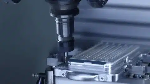
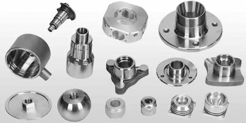
To counter this, it is important to concentrate on precision mold component manufacturing so that the component fits in immediately and no tolerance issues of mold components as usually felt is encountered.
Typical Tolerance Issues Found in Mold Components
Positional or dimensional variances that inhibit fit and functionality are the most common tolerance problems in mold components, and are usually not detected until the entire assembly or production is complete. Guide pin and bushing misalignment e.g. occurs due to positional tolerances failing to be held during machining resulting in binding or uneven movement.
Guide Pin and Bushing Misalignment
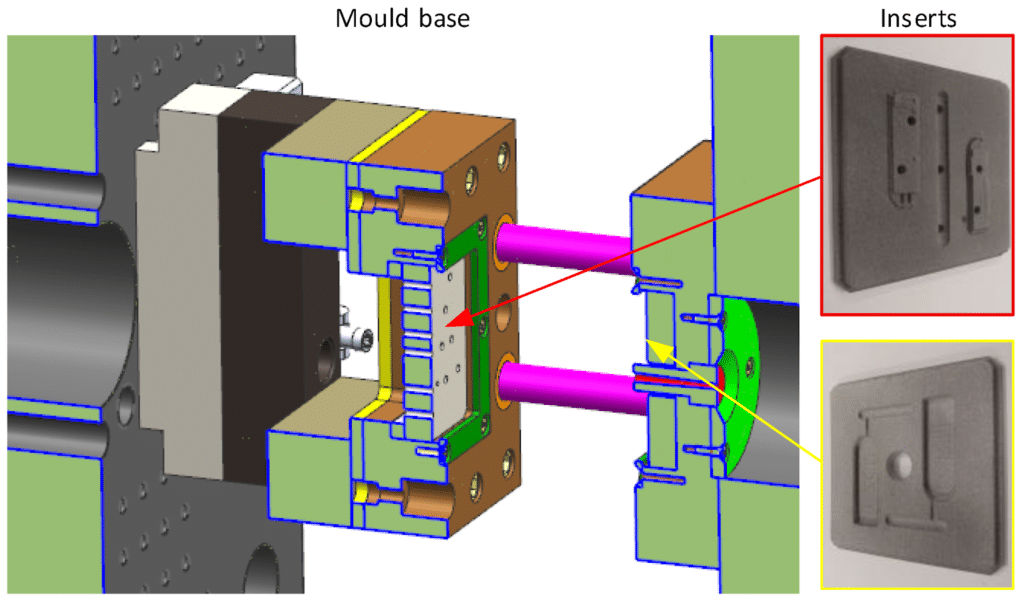
Insert fit variation This is where resin can leak out or wear out faster due to undersized or over size inserts that do not fit in the proper location. Corecorecavity mismatch This is due to dimensional incompatible behavior which does not allow uniform closure even between cores resulting in parting line defects.
Insert Fit Variation
Core–Cavity Mismatch
Ejector pin clearance issues, i.e. there are either too many or too few clearances, result in sticking parts or burr formation, which are not desired since they disrupt the cycle times.
Ejector Pin Clearance Problems
| Component | Typical Tolerance Issue | Resulting Problem |
| Guide pins | Positional deviation | Misalignment |
| Inserts | Oversize/undersize | Flash or wear |
| Ejector pins | Excess clearance | Burrs, sticking |
This table outlines key issues, highlighting how they manifest in mold component fit issues.
How Tolerance Stack-Up Causes Mold-Level Failures
Tolerance stack-up leads to failures at the mold level by enabling individual component tolerances to build up, and make small component tolerances into huge system variations. Individual tolerances may pass inspection on their own, but when combined e.g. in multi-cavity alignments, they are beyond operational limits.
Why Individual Tolerances Accumulate
The distinction between part level tolerance (single component checks) and system-level tolerance (assembled performance) is vital with the latter considering interactions such as thermal expansion or assembly forces.
Part-Level vs. System-Level Tolerance
An awareness of essential tolerances key tolerances in precision mold manufacturing in the manufacturing of precision molds, will be helpful in predicting and avoiding such stacks in tolerance stack-up within molds.
Precision Mold Making as the Foundation for Component Accuracy
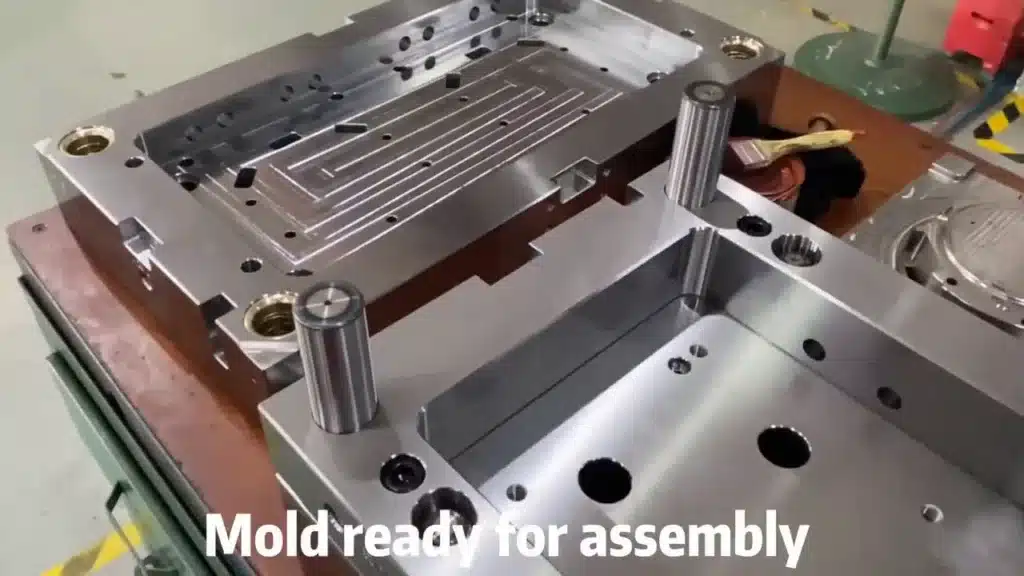
Precision mold making defines the accuracy of the components by focusing on the control of the system in the entire system where each stage of the design to assembly reduces the variances to an absolute minimum. This is a method more than mere machining since it involves strict verification to make it reproducible.
Precision Mold Making and System Control
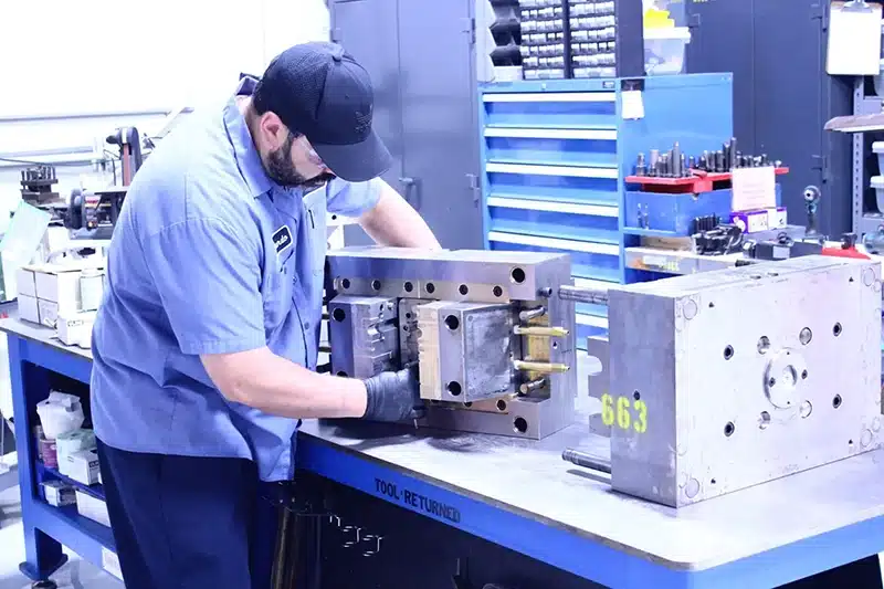
Inspect and assembly discipline are important, whereby tools such as CMM are used to identify deviations at an early stage, and standardized procedures are used to ensure fits.
Role of Inspection and Assembly Discipline
Understanding precision mold making fundamentals making highlights the importance of considering the entire picture of mold assembly tolerance issues avoidance.
Machining Accuracy Limits and Their Impact on Mold Components
Machining accuracy limits affect the component of mold because they establish the margin between the possible accuracy and the realistic repeatability where nominal accuracy (theoretical specifications) is different than repeatable accuracy (reliable results under factory conditions). Ignoring these limits in the specification process results in incompatible elements that do not work when put together.
Nominal vs. Repeatable Machining Accuracy
Tolerance specs should be advised by machining limits because overloading capabilities such as requesting sub-micron finishes on large areas is a source of more defecting due to tool wear or vibration.
Machining Limits in Tolerance Specification
It is important to understand the performance of CNC machining accuracy limits accuracy to make realistic expectations on precision mold component tolerances.
| Process | Typical Capability | Risk if Over-Specified |
| CNC milling | ±0.01–0.02 mm | Rework |
| EDM | ±0.005–0.01 mm | Instability |
| Grinding | ±0.002–0.005 mm | Cost escalation |
This table shows the capabilities and risks and makes more effective decisions in order to avoid the typical tolerance problems in mold parts.
How Mold Component Tolerance Issues Affect Part Consistency
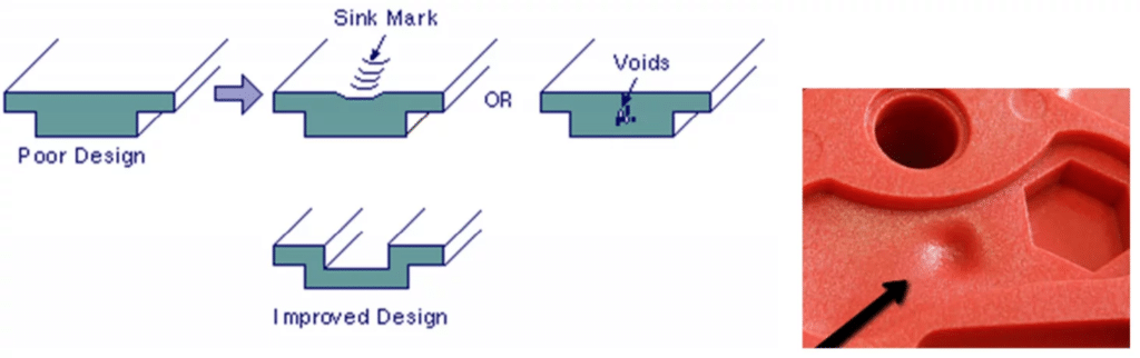
Part consistency is compromised by the mold component tolerance problems that create instabilities that create dimensional or cosmetic variation in the molded products. Stability of components, e.g. loose fits, is converted to imbalance in pressure, which causes warping or futile cavities.
Component Instability to Part Variation
The mismatch of the repeatability increases with time as the tolerances are aggravated by wear to become significant defects.
Inconsistency Increasing Over Time
This brings to focus the part inconsistency tolerance-related part inconsistency that is related to tolerance as a direct result of the untreated component issues.
How to Identify Tolerance Problems in Existing Molds
The detection of tolerance issues of already existing molds will be conducted by looking at check indicators such as dimensional deviations in CMM reports or presence of unaccounted assembly gaps. Evidence of chronic problems is in wear patterns, including non-even polishing of guides.
Inspection Indicators
Symptoms that are sometimes confused with process issues such as unreliable cycle times are actually caused by component tolerances which can only be verified through disassembly.
Wear Patterns
Symptoms Mistaken for Process Issues
| Symptom | Likely Cause |
| Flash variation | Insert fit tolerance |
| Dimensional drift | Guide system wear |
| Ejection inconsistency | Pin clearance |
This tabular information is a correlation of the symptoms with the cause which helps in the diagnosis of the mold component tolerance issues.
Preventing Tolerance Issues in Mold Component Design and Sourcing
The prevention of tolerance problems begins with the specification of functional tolerance, in which the specifications are based on the actual requirements and not the generic tightness. Selection of suppliers can be done in such a way that there is alignment between the ability of the suppliers and the ability to provide consistency.
Functional Tolerance Specification
Problem is caught early through inspection planning including in-process checks.
Supplier Capability Alignment
Importance of Inspection Planning
The steps are used to reinforce against the failures of mold assemblies.
Common Misunderstandings About Mold Component Tolerances
One of the misconceptions is that the components in spec are always perfectly fitting without the consideration of other factors in reality such as temperature that influences assembly. Stricter tolerances are perceived as a magic potion, but they may also bring in the emerging risks such as brittle.
Components Within Spec Always Fit Myth
Early assembly is not long-term valid, because wear unveils concealed variances with recurrences.
Tighter Tolerance Fixes All Issues
Initial Assembly Proves Long-Term Accuracy
Explaining these avoids failure in tolerance stack-up in molds.
Conclusion — Mold Stability Starts at the Component Level
To conclude, stable molds are based on the carefully balanced elements, in which the tolerance control starts with realistic specifications and goes down to verification to guarantee the systems are free of errors. The component-first approach changes the mindset to preventive engineering and the reduction of failures and an increase in reliability. The ability to consider tolerances as interdependent and not independent allows toolmakers to create molds that can be relied upon to perform even in extreme circumstances.