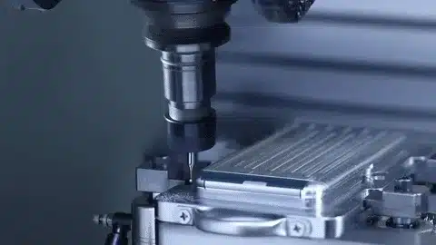
Defects of injection molds (sink marks, flash, short shots, etc.) are not often accidents but pre-established consequences of the choice made in the process of designing the mold. These problems are usually caused by the manner in which the geometry of the mold, flow paths and cooling mechanisms are set and not necessarily by the operators or machine settings during the production. Consumers assume that the problem of moulds is a result of processing problems, when in fact, most of the time the problem of the moulds is entrenched in mould design long before the manufacturing process.
A correct design of the molds will help to avoid the defects because they will remove the cause of the defects and not trying to fix the symptoms in the molding. Majority of defects of injection moulds are caused by choices that are made during mold design that occur even before cutting steel, rather than by alteration in molding settings after cutting.
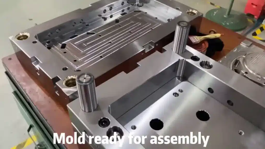
Why Most Mold Defects Originate in Design, Not Production
The majority of the mold flaws can be linked to their design stage assumptions that do not work in the actual environment where such symptoms as the inconsistency of parts will be observed in the production process but were predetermined by the previous decisions. When I was going through failed tools, a design-based approach is a 10-fold more efficient approach in comparison to retrofitting.
Difference Between Defect Symptoms and Root Causes
The design contains root causes, such as mismatched parting lines, and the end result is the symptoms, such as visible flash. This difference is significant since it moves away the reactive fixes towards preventive engineering.
Why Post-Trial Adjustments Are Limited in Effectiveness
Modifications such as escalation of clamp pressure may conceal flash but may hasten wear in case the design is not created to support. The key point is that true solution demands redesign and that is why there is a need of injection mold design and manufacturing processes are essential for defect prevention.
Sink Marks and Warpage — Geometry and Cooling Design Failures
Sink Marks and Warpage Geometry and Cooling Design Failures.
The typical examples of defects that are produced by uneven material shrinkage are sink marks and warpage, which are often caused by geometry or cooling defects that were trapped into the design. Tweaking such as slower cooling processing would make a small difference, but this could not address the natural imbalances.
How Wall Thickness and Cooling Imbalance Cause These Defects
Thicker pieces of the material cool more slowly, resulting in sinks; uneven cooling results in unequal shrinkage and warping. These can be forecasted in case flow simulations are applied at an early stage.
Why Processing Cannot Fully Compensate
Increased hold pressure will decrease sinks but may flash in other areas; design should be made to be consistent. Such trade-offs can be avoided by using these considerations in the custom injection mold design process prevents such trade-offs.
| Defect | Design Root Cause | Prevention Strategy |
| Sink marks | Uneven wall thickness | Uniform geometry |
| Warpage | Poor cooling layout | Balanced cooling design |
This is a table which gives root causes of injection mold defects, with the roles of design highlighted.
Flash, Burrs, and Parting Line Issues
Flash and burrs are the escaping molten material that usually subsequently leaves the cavity due to design tolerances that do not consider the clamp force as well as thermal expansion. These are not mere cosmetic but they are structural weaknesses.
Role of Parting Line Design and Clamp Force Assumptions
Misaligned parting lines or lack of shut-off permit leakage; tolerances should be defined by design with regard to machine capabilities.
Why Flash Indicates Design Tolerance Problems
It indicates pressure gaps, which may be the result of ignored wear; tight tolerances prohibit the same. The Maintaining critical mold tolerances is key to avoiding these in precision applications.
Short Shots, Weld Lines, and Flow-Related Defects
The short shot and the weld line are caused by failure to fill completely or the fusion of the material and this is directly related to the flow path design. These flaws affect strength and look, and more frequently cause redesign than parameter adjustments.
Gate Location and Runner Balance
Unoptimal gates result in hesitation that results in shorts; the unbalanced runners result in a weak weld line at the intersection of flows.
Flow Hesitation Caused by Design Constraints
Flow is constrained by narrow channels or sharp corners; simulations detect these. Understanding the mold design impact on quality and cost helps to understand the influence of the decisions on efficiency.
Surface Defects and Cosmetic Quality Issues
In the form of surface defects such as jetting or burn marks are a result of the interaction between the mold and the material and depend on venting and surface finish set in design. They are difficult to repair after construction.
How Surface Finish, Venting, and Steel Condition Affect Appearance
Poor ventilation traps air leading to burns, rough surfaces to imperfections. Design should have adequate vents and polish.
These issues highlight mold surface finish effects on final parts, where preventive design saves polishing time.
Premature Wear, Damage, and Tool Life–Related Defects
Premature wear is in the form of piting or cracking and shortening of the tool life and giving inconsistent parts.
Relationship Between Steel Selection, Hardness, and Wear
Connection among Steel Choose, Hardness, and Wear.
Why Material Choice Is a Design Decision
It balances cost and durability; poor choices lead to early failures. Proper mold steel selection extends life and maintains quality.
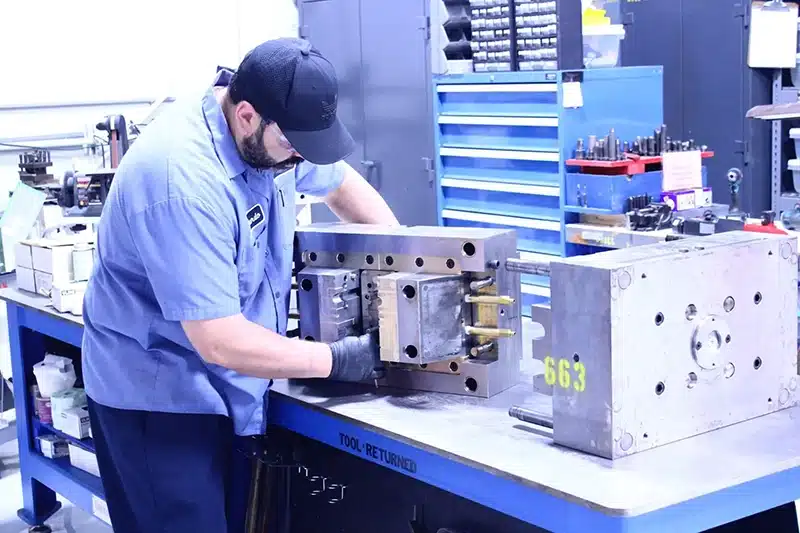
Why Repeated Mold Trials Are Often a Design Problem
It is at the price of cost and durability; inept decisions may cause premature failures. Quality and life are extended by proper choice of mold steel.
How Design Assumptions Fail During T1/T2 Trials
The expected rates of flow may not correspond to the real resin conduct and may need adjustments.
Why Repeated Trials Increase Cost and Delay
They use resources; their design reduces the resources. Good injection injection mold trial optimization starts with robust design.
The Cost of Ignoring Defect Prevention in Mold Design
Failure to prevent increases cost in terms of rework and lost production with flaws in design that increase over time.
Cost Escalation Due to Rework and Downtime
Flaws put work stops, exploding production costs.
Long-Term Impact on Tooling ROI
Unprofessional designs are life-stopping by lowering the ROI; preemptive focus is life-prolonging. These poor mold design consequences are avoidable with upfront analysis.
Precision Mold Design as the Foundation of Defect Prevention
Accuracy during the design process guarantees that tolerances and characteristics match what is required and defects are eliminated even in the “standard” molds.
Why Precision Matters Even for “Non-Precision” Parts
It is consistent; loose precision is provocative of variances.Adhering to precision mold making principles builds in prevention.
How Proper Mold Design Ensures Long-Term Part Consistency
Strong design is able to maintain performance over cycle, consistency in this case is due to balanced features.
Relationship Between Mold Quality and Consistency Across Production Cycles
Degradation is avoided by well-constructed cooling and geometry, making parts stable.
This ties into mold quality and part consistency, where design is the linchpin.
Conclusion — Defect Prevention Starts Before Tooling Begins
To conclude, the most effective way to deal with defects is to consider the design of molds because it will eliminate the causes of the problems ahead of time. Effective design of molds helps to avoid defects by dealing with their causes at an early stage, minimizing tests, repair, and ROP. Through analytical design, engineers are able to attain sound, cost-efficient production that is able to survive in the real world.